Preface
First of all, thank you for purchasing SK600 series frequency converters. SK600 series frequency converters are high-performance general-purpose current vector frequency converters, which can realize asynchronous motor and permanent magnet synchronous motor control, with user programmable functions, background monitoring software, communication bus functions, supporting multiple PG cards, etc., with powerful functions. It can be used for driving textile, papermaking, wire drawing, machine tools, packaging, food, fans, pumps and various automated production equipment.
This manual introduces the functional characteristics and usage methods of SK600 series frequency converters, including product selection, parameter setting, operation debugging, maintenance inspection, etc. Please be sure to read this manual carefully before use. Equipment supporting manufacturers please send this manual to end users with the equipment for subsequent reference.
Product Introduction
SK600 frequency converters have obvious improvements in the following aspects:
- Rich voltage levels: Support six voltage levels: single-phase 220V, three-phase 220V, three-phase 380V, three-phase 480V, three-phase 690V, three-phase 1140V.
- Rich motor type support: Support vector control of three-phase AC asynchronous motors and three-phase AC permanent magnet synchronous motors.
- Rich control methods: In addition to speed sensor vector control, sensorless vector control, V/F control, it also supports V/F separation control.
- Rich field buses: Support four buses: Modbus - RTU, Profibus - DP, CANlink, CANopen.
- Rich encoder types: Support differential encoders, open collector encoders, resolvers, UVW encoders, etc.
- Brand new sensorless vector control algorithm: Brand new SVC (Sensorless Vector Control) brings better low-speed stability, stronger low-frequency load capacity, and supports torque control of SVC.
- Support user programmable: Through PC60PC1 user programmable card, users can realize secondary development functions, and can write programs in ladder diagram and other ways.
- Powerful background software: The background software can realize functions such as uploading, downloading, and real-time oscilloscope of frequency converter parameters.
- More abundant functions:
| Function | Description |
|---|---|
| Virtual input/output IO | Can flexibly realize various simple logic functions |
| Motor overheat protection | After selecting PC60IO1 expansion card, AI3 can receive motor temperature sensor input (PT100, PT1000) to realize motor overheat protection |
| Fast current limiting | Avoid frequent overcurrent faults of frequency converters |
| Multi-motor switching | With four sets of motor parameters, can realize four motor switching control |
| Restore user parameters | This function supports customers to save or restore their own set parameters |
| Higher precision AIAO | Through factory calibration (can also be field calibrated), AIAO precision can reach within 20mv |
| User-customized parameter display | Users can customize the function parameters that need to be displayed |
| User changed parameter display | Users can view the function parameters that have been modified |
| Optional fault handling methods | Users can determine the action mode of the frequency converter after a specific fault occurs according to needs: free stop, deceleration stop, continue running. Can also choose the frequency when continuing to run. |
| PID parameter switching | With two sets of PID parameters, can be switched through terminals or automatically switched according to deviation |
| PID feedback loss detection | Set PID feedback loss detection value to realize protection during PID operation |
| DIDO positive and negative logic | User independently sets the positive and negative logic of DIDO |
| DIDO response delay | User independently sets DIDO response delay time |
| Instant stop without stopping | Ensure that the frequency converter continues to run for a short time when there is an instantaneous power failure or sudden voltage drop |
| Timing operation | Support maximum 6500 minutes timing operation |
| User programmable | External programmable card realizes user secondary development |
Precautions
- To illustrate the details of the product, the diagrams in this manual are sometimes in a state where the outer cover or safety cover is removed. When using this product, please be sure to install the shell or cover according to regulations, and operate according to the content of the manual.
- The illustrations in this manual are for illustration only and may differ from the product you ordered.
- Our company is committed to continuous improvement of products, product functions will be continuously upgraded, and the information provided is subject to change without notice.
- If you have any problems during use, please contact our regional agents or directly contact our customer service center.
Unpacking Inspection
When unpacking, please carefully confirm:
- Whether the model and rated value of the inverter on the nameplate are consistent with your order. The box contains your ordered machine, product certificate, user operation manual and warranty card.
- Whether the product is damaged during transportation; If you find any missing or damaged items, please contact our company or your supplier immediately for solution.
First Use
For users who use this product for the first time, they should read this manual carefully. If you have any doubts about some functions and performance, please consult our technical support personnel for help, which is beneficial to the correct use of this product.
Connection with Peripheral Equipment
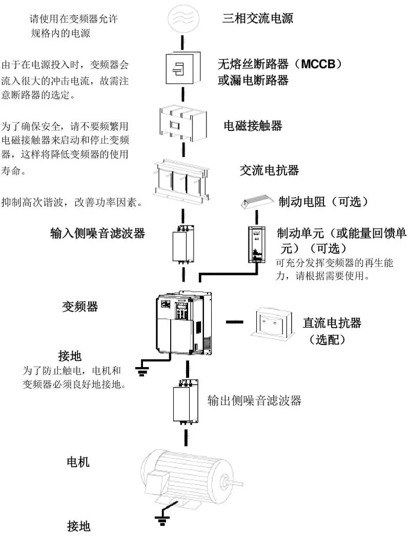
Please use three-phase AC power within the allowed specifications of the frequency converter. Since a large inrush current will flow into the frequency converter when the power is turned on, attention should be paid to the selection of the circuit breaker. To ensure safety, do not frequently use electromagnetic contactors to start and stop the frequency converter, which will reduce the service life of the frequency converter.
| Equipment | Description |
|---|---|
| No-fuse circuit breaker (MCCB) or leakage circuit breaker | Used to protect the circuit, prevent overload, short circuit and other faults |
| Electromagnetic contactor | Not recommended for frequent starting and stopping of frequency converters |
| AC reactor | Suppress high-order harmonics and improve power factor |
| Brake resistor (optional) | Consume motor regeneration energy |
| Brake unit (or energy feedback unit) (optional) | Give full play to the regeneration capacity of the frequency converter, please use it according to needs |
| DC reactor (optional) | Improve power supply characteristics |
| Grounding | To prevent electric shock, the motor and frequency converter must be well grounded |
| Output side noise filter | Reduce electromagnetic interference on the output side |
| Motor | Equipment driven by frequency converter |
Note
1. Do not install capacitors or surge suppressors on the output side of the frequency converter, which will cause failure of the frequency converter or damage to the capacitor and surge suppressor.
2. The input / output (main circuit) of the frequency converter contains harmonic components, which may interfere with communication equipment attached to the frequency converter. Therefore, install anti-interference filters to minimize interference.
3. For details of peripheral equipment and accessories, refer to the peripheral equipment selection manual.
1. Safety Information and Precautions
1.1 Safety Definitions
In this manual, safety precautions are divided into the following two categories:
Note
Dangers caused by failure to operate as required may result in moderate or minor injuries and equipment damage
Danger
Dangers caused by failure to operate as required may result in serious injuries or even death;
Please read this chapter carefully when installing, debugging and maintaining this system, and be sure to follow the safety precautions required in this chapter. Any injury and loss caused by illegal operation has nothing to do with our company.
1.2 Safety Matters
| Use Stage | Safety Level | Matters |
|---|---|---|
| Before installation | Danger | ● Do not install if the control system is found to be flooded, missing parts or damaged when unpacking!● Do not install if the packing list does not match the actual name! |
| Note | ● Handle with care when carrying, otherwise there is a danger of damaging the equipment!● Do not use damaged drives or frequency converters with missing parts. There is a danger of injury!● Do not touch the components of the control system with your hands, otherwise there is a danger of electrostatic damage! | |
| During installation | Danger | ● Please install on metal and other flame-retardant objects; Keep away from combustibles. Otherwise, it may cause fire!● Do not arbitrarily twist the fixing bolts of equipment components, especially bolts with red marks! |
| Note | ● Do not let wire ends or screws fall into the drive. Otherwise, it will cause damage to the drive!● Please install the drive in a place with less vibration and avoid direct sunlight.● When two or more frequency converters are placed in the same cabinet, pay attention to the installation position to ensure heat dissipation effect. | |
| During wiring | Danger | ● Must follow the guidance of this manual, constructed by professional electrical engineers, otherwise unexpected dangers will occur!● A circuit breaker must be installed between the frequency converter and the power supply, otherwise fire may occur!● Please confirm that the power supply is in a zero energy state before wiring, otherwise there is a danger of electric shock!● Please properly ground the frequency converter according to the standard, otherwise there is a danger of electric shock! |
| Note | ● Never connect the input power to the output terminals (U, V, W) of the frequency converter. Pay attention to the marks of the terminals, do not connect wrong wires! Otherwise, it will cause damage to the frequency converter!● Please refer to the manual’s recommendations for the wire diameter used. Otherwise, accidents may occur!● Never connect the brake resistor directly between the DC bus (+), (-) terminals. Otherwise, it may cause fire!● The encoder must use shielded wire, and the shield layer must be reliably grounded at one end! | |
| Before power-on | Danger | ● Please confirm whether the voltage level of the input power supply is consistent with the rated voltage level of the frequency converter; Whether the wiring positions on the power input terminals (R, S, T) and output terminals (U, V, W) are correct; And check whether there is a short circuit in the peripheral circuit connected to the drive, and whether the connected lines are tight, otherwise it will cause damage to the drive!● No withstand voltage test is required for any part of the frequency converter, and the product has been tested at the factory. Otherwise, it will cause accidents! |
| Note | ● The frequency converter must be powered on after the cover is closed. Otherwise, electric shock may occur!● The wiring of all peripheral accessories must follow the guidance of this manual and be correctly wired according to the circuit connection method provided in this manual. Otherwise, it will cause accidents! | |
| After power-on | Danger | ● Do not open the cover after power-on. Otherwise, there is a danger of electric shock!● Do not touch the drive and peripheral circuits with wet hands. Otherwise, there is a danger of electric shock!● Do not touch any input and output terminals of the frequency converter. Otherwise, there is a danger of electric shock!● At the initial stage of power-on, the frequency converter automatically performs safety detection on the external high-voltage circuit. At this time, never touch the U, V, W terminals of the drive or the motor terminals, otherwise there is a danger of electric shock! |
| Note | ● If parameter identification is required, pay attention to the danger of injury when the motor rotates. Otherwise, it may cause accidents!● Do not arbitrarily change the manufacturer’s parameters of the frequency converter. Otherwise, it may cause damage to the equipment! | |
| During operation | Danger | ● Do not touch the cooling fan and discharge resistor to test the temperature. Otherwise, it may cause burns!● Non-professional technicians should not detect signals during operation. Otherwise, it may cause personal injury or equipment damage! |
| Note | ● During the operation of the frequency converter, avoid things falling into the equipment. Otherwise, it will cause damage to the equipment!● Do not use contactors to control the start and stop of the frequency converter. Otherwise, it will cause damage to the equipment! | |
| During maintenance | Danger | ● Personnel without professional training should not repair and maintain the frequency converter. Otherwise, it will cause personal injury or equipment damage!● Do not repair and maintain the equipment with electricity. Otherwise, there is a danger of electric shock!● Confirm that the input power of the frequency converter is cut off for 10 minutes before performing maintenance and repair on the drive. Otherwise, the residual charge on the capacitor will cause harm to people!● All pluggable plug-ins must be plugged and unplugged when power is off!● After replacing the frequency converter, parameter Settings and checks must be performed. |
1.3 Precautions
- Motor insulation check: The motor should be checked for insulation before first use, reuse after long-term storage and regular inspection to prevent damage to the frequency converter due to insulation failure of the motor windings. During insulation check, be sure to separate the motor connection from the frequency converter, it is recommended to use a 500V voltage type megohmmeter, and ensure that the measured insulation resistance is not less than 5MΩ.
- Motor thermal protection: If the selected motor does not match the rated capacity of the frequency converter, especially when the rated power of the frequency converter is greater than the rated power of the motor, be sure to adjust the motor protection related parameters in the frequency converter or add a thermal relay in front of the motor to protect the motor.
- Operation above power frequency: This frequency converter can provide 0Hz - 500Hz output frequency. If the customer needs to run above 50Hz, please consider the bearing capacity of the mechanical device.
- Vibration of mechanical devices: The frequency converter may encounter the mechanical resonance point of the load device at some output frequencies, which can be avoided by setting the jump frequency parameters in the frequency converter.
- About motor heating and noise: Because the output voltage of the frequency converter is PWM wave, which contains certain harmonics, the temperature rise, noise and vibration of the motor will be slightly increased compared with power frequency operation.
- When there are voltage-sensitive devices or capacitors to improve power factor on the output side: The output of the frequency converter is PWM wave, and if capacitors to improve power factor or lightning protection varistors are installed on the output side, it is easy to cause instantaneous overcurrent of the frequency converter or even damage the frequency converter. Please do not use.
- Contactor and other switching devices used at input and output ends of frequency converter: If a contactor is installed between the power supply and the input end of the frequency converter, it is not allowed to use this contactor to control the start and stop of the frequency converter. If it is necessary to use this contactor to control the start and stop of the frequency converter, the interval should not be less than one hour. Frequent charging and discharging will reduce the service life of the capacitor in the frequency converter. If there are contactors and other switching devices between the output end and the motor, ensure that the frequency converter is switched on and off when there is no output, otherwise it is easy to cause damage to the modules in the frequency converter.
- Lightning shock protection: This series of frequency converters is equipped with lightning overcurrent protection devices, which have a certain self-protection ability against induced lightning. For areas with frequent lightning, customers should also install protection at the front end of the frequency converter.
- Altitude and derating use: In areas with altitude above 1000m, due to the thin air, the heat dissipation effect of the frequency converter becomes worse, so it is necessary to derate use. Please consult our company for technical advice in this case.
- Some special uses: If the customer needs to use methods other than the recommended wiring diagram provided in this manual, such as common DC bus, please consult our company.
- Attention when scrapping frequency converters: Electrolytic capacitors in the main circuit and electrolytic capacitors on printed circuit boards may explode when incinerated. Plastic parts will produce toxic gases when incinerated. Please handle as industrial waste.
- About suitable motors:
- Standard suitable motors are four-pole squirrel cage asynchronous induction motors or permanent magnet synchronous motors. If it is not the above motor, please select the frequency converter according to the rated current of the motor.
- The cooling fan of non-frequency conversion motor is coaxially connected with the rotor shaft, and the cooling effect of the fan decreases when the speed decreases. Therefore, forced exhaust fans should be added or replaced with frequency conversion motors in situations where the motor overheats;
- The frequency converter has built-in standard parameters for suitable motors. It is necessary to identify motor parameters or modify default values according to actual conditions to better match actual values, otherwise it will affect operation effect and protection performance;
- Because short circuit inside the cable or motor will cause frequency converter alarm, and even explosion. Therefore, please first test the insulation short circuit of the initially installed motor and cable, and also conduct this test frequently in daily maintenance. Note that when doing this test, be sure to disconnect the frequency converter from all parts being tested.
2. Inverter Model and Technical Parameters
2.1 SK600 Series Inverter Model and Technical Parameters
| Three-phase power: 380V, 50/60Hz | Power capacity (KVA) | Input current (A) | Output current (A) | G type machine (KW) | P type machine (KW) |
|---|---|---|---|---|---|
| SK600T0.7GB | 1.5 | 3.4 | 2.1 | 0.75 | 1 |
| SK600T1.5GB | 3.0 | 5.0 | 3.8 | 1.5 | 2 |
| SK600T2.2GB | 4.0 | 5.8 | 5.1 | 2.2 | 3 |
| SK600T3.7GB | 5.9 | 10.5 | 9.0 | 3.7 | 5 |
| SK600T5.5GB | 8.9 | 14.6 | 13.0 | 5.5 | 7.5 |
| SK600T7.5GB | 11.0 | 20.5 | 17.0 | 7.5 | 10 |
| SK600T11GB | 17.0 | 26.0 | 25.0 | 11.0 | 15 |
| SK600T15GB | 21.0 | 35.0 | 32.0 | 15.0 | 20 |
| SK600T18.5G | 24.0 | 38.5 | 37.0 | 18.5 | 25 |
| SK600T22G | 30.0 | 46.5 | 45.0 | 22 | 30 |
| SK600T30G | 40.0 | 62.0 | 60.0 | 30 | 40 |
| SK600T37G | 57.0 | 76.0 | 75.0 | 37 | 50 |
| SK600T45G | 69.0 | 92.0 | 91.0 | 45 | 60 |
| SK600T55G | 85.0 | 113.0 | 112.0 | 55 | 70 |
| SK600T75G | 114.0 | 157.0 | 150.0 | 75 | 100 |
| SK600T90G | 134.0 | 180.0 | 176.0 | 90 | 125 |
| SK600T110G | 160.0 | 214.0 | 210.0 | 110 | 150 |
| SK600T132G | 192.0 | 256.0 | 253.0 | 132 | 175 |
| SK600T160G | 231.0 | 307.0 | 304.0 | 160 | 210 |
| SK600T200G | 250.0 | 385.0 | 377.0 | 200 | 260 |
| SK600T220G | 280.0 | 430.0 | 426.0 | 220 | 300 |
| SK600T250G | 355.0 | 468.0 | 465.0 | 250 | 350 |
| SK600T280G | 396.0 | 525.0 | 520.0 | 280 | 370 |
| SK600T315G | 445.0 | 590.0 | 585.0 | 315 | 500 |
| SK600T355G | 500.0 | 665.0 | 650.0 | 355 | 420 |
| SK600T400G | 565.0 | 785.0 | 725.0 | 400 | 530 |
| SK600T450G | 630.0 | 883.0 | 820.0 | 450 | 600 |
2.2 Technical Specifications
| Item | Specification |
|---|---|
| Maximum frequency | Vector control: 0 - 500Hz V/F control: 0 - 3200Hz |
| Carrier frequency | 0.5kHz - 16kHz can automatically adjust the carrier frequency according to load characteristics |
| Input frequency resolution | Digital setting: 0.01Hz Analog setting: maximum frequency ×0.025% |
| Control method | Open loop vector control (SVC) Closed loop vector control (FVC) V/F control |
| Starting torque | G type machine: 0.5Hz/150% (SVC); 0Hz/180% (FVC) P type machine: 0.5Hz/100% |
| Speed regulation range | 1 : 100 (SVC) 1 : 1000 (FVC) |
| Speed stabilization accuracy | ±0.5% (SVC) ±0.02% (FVC) |
| Torque control accuracy | ±5% (FVC) |
| Overload capacity | G type machine: 150% rated current 60s; 180% rated current 3s P type machine: 120% rated current 60s; 150% rated current 3s |
| Torque boost | Automatic torque boost; Manual torque boost 0.1% - 30.0% |
| V/F curve | Three ways: linear; Multi-point; (1.2 power, 1.4 power, 1.6 power, 1.8 power, 2 power) N power V/F curve |
| V/F separation | 2 ways: full separation, semi-separation |
| Acceleration/deceleration curve | Linear or S acceleration/deceleration curve acceleration/deceleration method. Four acceleration/deceleration times, time range 0.0 - 6500.0s |
| DC braking | DC braking frequency: 0.00Hz - maximum frequency Braking time: 0.0s - 36.0s Braking action current value: 0.0% - 100.0% |
| Jog control | Jog frequency range: 0.00Hz - 50.00Hz. Jog acceleration/deceleration time 0.0s - 6500.0s |
| Simple PLC, multi-speed operation | Realize up to 16-speed operation through built-in PLC or control terminal |
| Built-in PID | Can easily realize process control closed-loop control system |
| Automatic voltage regulation (AVR) | When the grid voltage changes, it can automatically keep the output voltage constant |
| Overvoltage and overcurrent loss speed control | Automatically limit the current and voltage during operation to prevent frequent overcurrent and overvoltage tripping |
| Fast current limiting function | Minimize overcurrent faults and protect the normal operation of the frequency converter |
| Torque limitation and control | “Excavator” characteristic, automatically limit the torque during operation to prevent frequent overcurrent tripping; Closed-loop vector mode can realize torque control |
| Excellent performance | Realize asynchronous motor and synchronous motor control with high-performance current vector control technology |
| Personalized functions | Instant stop without stopping: When instantaneous power failure occurs, the voltage drop is compensated by load feedback energy, and the frequency converter continues to run for a short time Fast current limiting: Avoid frequent overcurrent faults of the frequency converter Virtual IO: Five groups of virtual DIDO, can realize simple logic control Timing control: Timing control function, set time range 0.0Min - 6500.0Min Multi-motor switching: Four sets of motor parameters, can realize four motor switching control Multi-thread bus support: Support four field buses: RS - 485, Profibus - DP, CANlink, CANopen Multi-encoder support: Support differential, open collector, UVW, resolver, sine and cosine encoders, etc. User programmable: Optional user programmable card, can realize secondary development Powerful background software: Support frequency converter parameter operation and virtual oscilloscope function. The internal state of the frequency converter can be monitored graphically through the virtual oscilloscope |
| Command source | Operation panel given, control terminal given, serial communication port given. Can be switched in a variety of ways |
| Operation | Frequency source: 10 kinds of frequency sources: digital given, analog voltage given, analog current given, pulse given, serial port given. Can be switched in a variety of ways Auxiliary frequency source: 10 kinds of auxiliary frequency sources. Can flexibly realize auxiliary frequency fine tuning, frequency synthesis |
| Input terminal | Standard: 5 digital input terminals, one of which supports high-speed pulse input up to 100kHz 2 analog input terminals, one only supports 0 - 10V voltage input, one supports 0 - 10V voltage input or 4 - 20mA current input Expansion capability: 5 digital input terminals 1 analog input terminal, support - 10 - 10V voltage input, and support PT100\PT1000 |
| Output terminal | Standard: 1 high-speed pulse output terminal (optional as open collector type), support 0 - 100kHz square wave signal output 1 digital output terminal 1 relay output terminal 1 analog output terminal, support 0 - 20mA current output or 0 - 10V voltage output Expansion capability: 1 digital output terminal 1 relay output terminal 1 analog output terminal, support 0 - 20mA current output or 0 - 10V voltage output |
| Display and keyboard operation | LED display: display parameters LCD display: optional, Chinese/English prompt operation content Parameter copy: Can realize fast parameter replication through LCD operation panel option Key lock and function selection: Realize partial or full lock of keys, define the scope of action of some keys to prevent misoperation |
| Protection functions | Power-on motor short circuit detection, input and output phase loss protection, overcurrent protection, overvoltage protection, undervoltage protection, overheat protection, overload protection, etc. |
| Optional accessories | LCD operation panel, brake components, IO expansion card 1, IO expansion card 2, user programmable card, RS485 communication card, Profibus - DP communication card, CANlink communication card, CANopen communication card, differential input PG card, UVW differential input PG card, resolver PG card, OC input PG card |
| Environment | Use place: indoor, not exposed to direct sunlight, no dust, corrosive gas, flammable gas, oil mist, water vapor, dripping water or salt, etc. Altitude: below 1000m Ambient temperature: - 10℃ - + 40℃ (when ambient temperature is 40℃ - 50℃, please derate use) Humidity: less than 95%RH, no water condensation Vibration: less than 5.9m/s² (0.6g) Storage temperature: - 20℃ - + 60℃ |
2.3 SK600 Inverter Appearance and Installation Hole Dimension (mm)
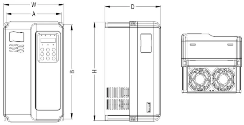
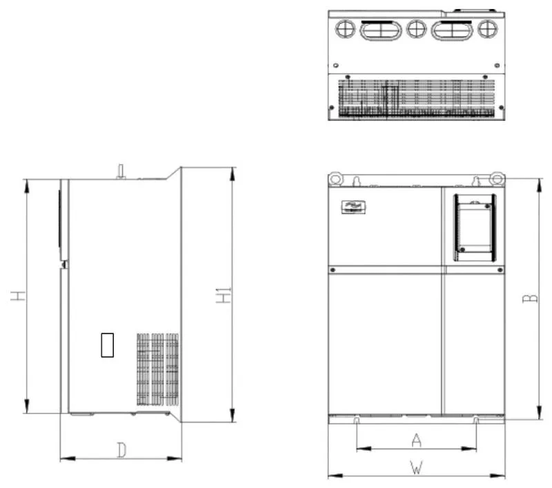
| Power (kw) | Installation dimension (mm)AxB | External dimension (mm)HxWxD | Installation hole diameter (mm)d |
|---|---|---|---|
| 1.5 - 2.2 | 113x172 | 186x125x164 | 5 |
| 4 - 7.5 | 148x236 | 248x160x183 | 5 |
| 11 - 22 | 190x305 | 322x208x192 | 6 |
| 30 - 37 | 235x447 | 463x285x228 | 6.5 |
| 45 - 75 | 260x580 | 600x385x265 | 7 |
| 90 - 132 | 343x678 | 700x473x307 | 9 |
| 160 - 200 | 449x903 | 930x579x380 | 12.5 |
| 220 - 315 | 420x1030 | 1060x650x377 | 12.5 |
| 355 - 400 | 520x1300 | 1360x800x388 | 12.5 |
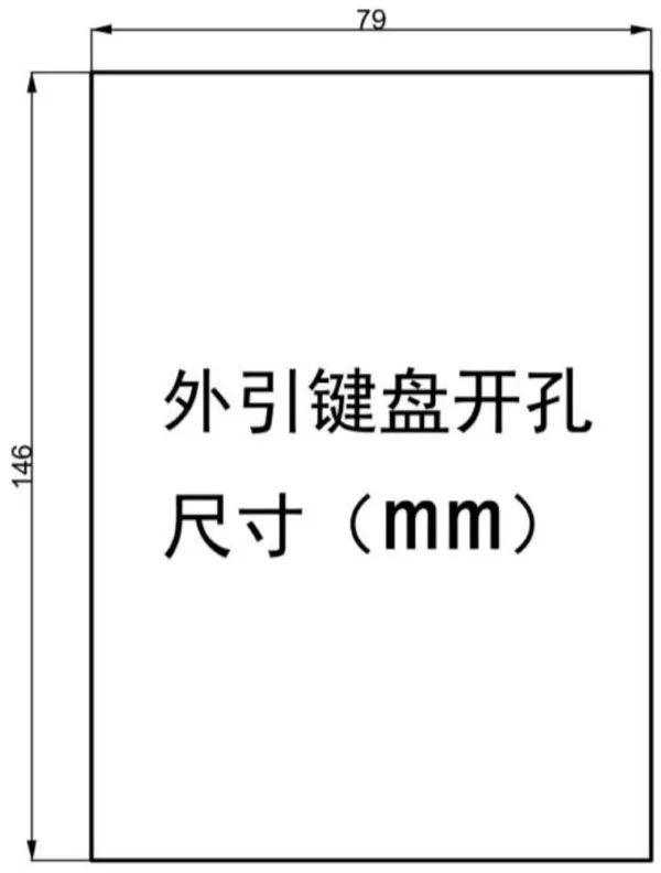
2.4 SK600 Inverter External Keyboard Opening Dimension
3. Daily Maintenance and Maintenance of Inverters
3.1 Daily Maintenance
Due to the influence of ambient temperature, humidity, dust and vibration, the internal components of the frequency converter will age, leading to potential failures of the frequency converter or reducing its service life. Therefore, it is necessary to carry out daily and regular maintenance and maintenance of the frequency converter.
- Daily inspection items:
- Whether the sound of the motor changes abnormally during operation.
- Whether the motor vibrates during operation.
- Whether the installation environment of the frequency converter changes.
- Whether the cooling fan of the frequency converter works normally.
- Whether the frequency converter is overheated.
- Daily cleaning:
- The frequency converter should always be kept clean.
- Effectively remove dust on the surface of the frequency converter to prevent dust from entering the inside of the frequency converter, especially metal dust.
- Effectively remove oil from the cooling fan of the frequency converter.
3.2 Regular Inspection
Please regularly check places that are difficult to check during operation.
- Regular inspection items:
- Check the air duct and clean it regularly.
- Check whether the screws are loose.
- Check whether the frequency converter is corroded.
- Check whether the wiring terminals have arc marks.
- Main circuit insulation test.
- Reminder: When measuring the motor insulation resistance with a megohmmeter (please use a DC 500V megohmmeter), the main circuit line should be disconnected from the frequency converter. Do not test the insulation of the control circuit with an insulation resistance meter, and no high voltage test is required (completed at the factory).
3.3 Replacement of Vulnerable Parts of Inverters
The vulnerable parts of the frequency converter are mainly cooling fans and filtering electrolytic capacitors, and their service life is closely related to the use environment and maintenance conditions. The general service life is:
| Device name | Service life |
|---|---|
| Fan | 2 - 3 years |
| Electrolytic capacitor | 4 - 5 years |
Users can determine the replacement period according to the running time.
- Cooling fan:
- Possible damage reasons: bearing wear, blade aging.
- Judgment standard: whether there are cracks in the fan blades, whether there is abnormal vibration sound when starting.
- Filter electrolytic capacitor:
- Possible damage reasons: poor input power quality, high ambient temperature, frequent load jumps, electrolyte aging.
- Judgment standard: whether there is liquid leakage, whether the safety valve has protruded, measurement of electrostatic capacitance, measurement of insulation resistance.
3.4 Storage of Inverters
After users purchase frequency converters, attention must be paid to the following points for temporary storage and long-term storage:
- When storing, try to put it into our company’s packaging box according to the original packaging.
- Long-term storage will lead to deterioration of electrolytic capacitors. It must be ensured that the power is turned on once within 2 years, and the power-on time is at least 5 hours. The input voltage must be slowly increased to the rated value with a voltage regulator.
3.5 Warranty Instructions for Inverters
- Free warranty only refers to the frequency converter itself. Under normal use, if failure or damage occurs, our company is responsible for 20 months warranty (from the date of manufacture, subject to the barcode on the machine), more than 20 months, reasonable maintenance fees will be charged.
- Within 20 months, if the following situations occur, a certain maintenance fee should be charged:
- Damage to the machine caused by the user’s failure to follow the provisions in the user manual.
- Damage caused by fire, flood, abnormal voltage, etc.
- Damage caused by using the frequency converter for non-normal functions.
- The service fee is calculated according to the unified standard of the manufacturer. If there is a contract, it will be handled according to the principle of contract priority.
4. Selection Guide for Inverter Brake Components
4.1 Selection Guide for Brake Components
The following selection table is a guide data, users can choose different resistance values and power according to the actual situation (but the resistance value must not be less than the recommended value in the table, the power can be large). The selection of brake resistance needs to be determined according to the power generated by the motor in the actual application system, which is related to system inertia, deceleration time, energy of potential energy load, etc., and needs to be selected by customers according to the actual situation. The greater the inertia of the system, the shorter the required deceleration time, and the more frequent the braking, the greater the power and smaller the resistance value of the brake resistance need to be selected.
- Selection of resistance value: During braking, almost all the regenerative energy of the motor is consumed in the brake resistance. According to the formula: $U*U/R = Pb$, where $U$ is the brake voltage for stable braking of the system (different systems are different, generally 700V for 380VAC system), and $Pb$ is the brake power.
- Selection of brake resistance power: In theory, the power of the brake resistance is consistent with the brake power, but considering derating to 70%. According to the formula: $0.7Pr = PbD$, $Pr$ is the power of the resistance, $D$ is the brake frequency (the proportion of the regenerative process in the entire working process). The brake frequency of elevators, unwinding and winding is 20% - 30%, that of centrifuges is 50% - 60%, that of accidental brake loads is 5%, and generally 10% is taken.
4.2 Inverter Brake Component Selection Table
| Inverter model | Recommended power of brake resistance | Recommended resistance value of brake resistance | Brake unit | Remarks |
|---|---|---|---|---|
| Single-phase 220V | ||||
| SK600S0.4GB | 80W | ≥200Ω | Standard built-in | No special instructions |
| SK600S0.7GB | 80W | ≥150Ω | Standard built-in | |
| SK600S1.5GB | 100W | ≥100Ω | Standard built-in | |
| SK600S2.2GB | 100W | ≥70Ω | Standard built-in | |
| Three-phase 220V | ||||
| SK600 - 2T0.4GB | 150W | ≥150Ω | ||
| SK600 - 2T0.75GB | 150W | ≥110Ω | Standard built-in | |
| SK600 - 2T1.1GB | 250W | ≥100Ω | ||
| SK600 - 2T2.2GB | 300W | ≥65Ω | No special instructions | |
| SK600 - 2T3.7GB | 400W | ≥45Ω | ||
| SK600 - 2T5.5GB | 800W | ≥22Ω | ||
| SK600 - 2T7.5GB | 1000W | ≥16Ω | ||
| SK600 - 2T11G | 1500W | ≥11Ω | Add “B” after the inverter model | |
| SK600 - 2T15G | 2500W | ≥8Ω | Built-in optional | |
| SK600 - 2T18.5G | 3.7kW | ≥8.0Ω | External | VFDBU - 35 - A |
| SK600 - 2T22G | 4.5kW | ≥8Ω | External | VFDBU - 35 - A |
| SK600 - 2T30G | 5.5kW | ≥4Ω | External | VFDBU - 70 - A |
| SK600 - 2T37G | 7.5kW | ≥4Ω | External | VFDBU - 70 - A |
| SK600 - 2T45G | 4.5kW×2 | ≥4Ω×2 | External | VFDBU - 70 - A×2 |
| SK600 - 2T55G | 5.5kW×2 | ≥4Ω×2 | External | VFDBU - 70 - A×2 |
| SK600 - 2T75G | 16kW | ≥1.2Ω | External | VFDBU - 200 - A |
| Three-phase 380V | ||||
| SK600T0.7GB | 150W | ≥300Ω | No special instructions | |
| SK600T1.5GB | 150W | ≥220Ω | ||
| SK600T2.2GB | 250W | ≥200Ω | ||
| SK600T3.7GB | 300W | ≥130Ω | Standard built-in | |
| SK600T5.5GB | 400W | ≥90Ω | ||
| SK600T7.5GB | 500W | ≥65Ω | ||
| SK600T11GB | 800W | ≥43Ω | ||
| SK600T15GB | 1000W | ≥32Ω | ||
| SK600T18.5 | 1300W | ≥25Ω | Add “B” after the inverter model | |
| SK600T22 | 1500W | ≥22Ω | Built-in optional | |
| SK600T30 | 2500W | ≥16Ω | ||
| SK600T37 | 3.7kW | ≥16.0Ω | External | VFDBU - 35 - B |
| SK600T45 | 4.5kW | ≥16Ω | External | VFDBU - 35 - B |
| SK600T55 | 5.5kW | ≥8Ω | External | VFDBU - 70 - B |
| SK600T75 | 7.5kW | ≥8Ω | External | VFDBU - 70 - B |
| SK600T90 | 4.5kW×2 | ≥8Ω×2 | External | VFDBU - 70 - B×2 |
| SK600T110 | 5.5kW×2 | ≥8Ω×2 | External | VFDBU - 70 - B×2 |
| SK600T132 | 6.5kW×2 | ≥8Ω×2 | External | VFDBU - 70 - B×2 |
| SK600T160 | 16kW | ≥2.5Ω | External | VFDBU - 200 - B |
| SK600T200 | 20kW | ≥2.5Ω | External | VFDBU - 200 - B |
| SK600T220 | 22kW | ≥2.5Ω | External | VFDBU - 200 - B |
| SK600T250 | 12.5kW×2 | ≥2.5Ω×2 | External | VFDBU - 200 - B×2 |
| SK600T280 | 14kW×2 | ≥2.5Ω×2 | External | VFDBU - 200 - B×2 |
| SK600T315 | 16kW×2 | ≥2.5Ω×2 | External | VFDBU - 200 - B×2 |
| SK600T355 | 17kW×2 | ≥2.5Ω×2 | External | VFDBU - 200 - B×2 |
| SK600T400 | 14kW×3 | ≥2.5Ω×3 | External | VFDBU - 200 - B×3 |
| SK600T450 | 15kW×3 | ≥2.5Ω×3 | External | VFDBU - 200 - B×3 |
Note: ×2 means two brake units with their respective brake resistors are used in parallel, and ×3 has the same meaning as ×2.
5. Mechanical and Electrical Installation of Inverters
5.1 Single-phase Inverter Main Circuit Terminal Description
| Terminal mark | Name | Description |
|---|---|---|
| L1、L2 | Single-phase power input terminal | Single-phase 220V AC power connection point |
| ( + )、( - ) | DC bus positive and negative terminals | Common DC bus input point |
| ( + )、PB | Brake resistor connection terminal | Connect brake resistor |
| U、V、W | Inverter output terminal | Connect three-phase motor |
| PE | Grounding terminal | Grounding terminal |
5.2 Three-phase Inverter Main Circuit Terminal Description
| Terminal mark | Name | Description |
|---|---|---|
| R、S、T | Three-phase power input terminal | AC input three-phase power connection point |
| ( + )、( - ) | DC bus positive and negative terminals | Common DC bus input point, connection point of external brake unit above 37kW |
| ( + )、PB | Brake resistor connection terminal | Brake resistor connection point below 30kW (below 15kW for 220V) |
| P、( + ) | External reactor connection terminal | External reactor connection point |
| U、V、W | Inverter output terminal | Connect three-phase motor |
| PE | Grounding terminal | Grounding terminal |
5.3 Wiring Precautions
- Input power L1, L2 or R, S, T: The input side wiring of the frequency converter has no phase sequence requirements.
- DC bus (+), (-)
- Note that there is still residual voltage on the DC bus (+), (-) terminals just after power failure. You must wait for the CHARGE light to go out and confirm that the power is off for 10 minutes before wiring, otherwise there is a danger of electric shock.
- When selecting external brake components for 37kW and above (18.5kW and above for 220V), note that the (+) and (-) polarities cannot be reversed, otherwise it will cause damage to the frequency converter or even fire.
- The wiring length of the brake unit should not exceed 10m, and twisted pair or tightly parallel double wires should be used for wiring.
- The brake resistor cannot be directly connected to the DC bus, which may cause damage to the frequency converter or even fire.
- Brake resistor connection terminals (+), PB
- The brake resistor connection terminals are only valid for models with built-in brake units confirmed below 30kW (below 15kW for 220V).
- The selection of brake resistor refers to the recommended value and the wiring distance should be less than 5m, otherwise it may cause damage to the frequency converter.
- External reactor connection terminals P, (+): For frequency converters with power above 75kW (above 37KW for 220V), the reactor is external. When assembling, remove the connection piece between the P and (+) terminals, and connect the reactor between the two terminals.
- Inverter output side U, V, W
- Capacitors or surge absorbers cannot be connected to the output side of the frequency converter, otherwise it will cause frequent protection of the frequency converter or even damage.
- When the motor cable is too long, due to the influence of distributed capacitance, it is easy to produce electrical resonance, which will cause damage to the motor insulation or produce large leakage current to make the frequency converter overcurrent protection. When the motor cable length is greater than 100m, an AC output reactor must be installed.
- Grounding terminal PE
- The terminal must be reliably grounded, and the grounding wire resistance must be less than 0.1Ω, otherwise it will cause abnormal operation or damage to the equipment.
- The grounding terminal and the power zero line N terminal cannot be shared.
6. Inverter Control Circuit Wiring Method
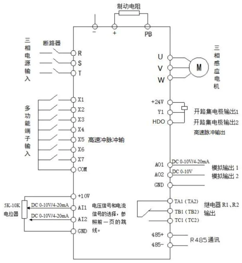
6.1 Control Circuit Wiring Diagram
6.2 Control Terminal Description
The control circuit terminal layout is as follows:
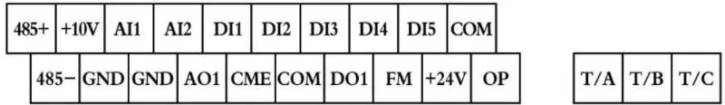
485 + 、+10V、AI1、AI2、DI1、DI2、DI3、DI4、DI5、COM、485 - 、GND、GND、AO1、CME、COM、D01、FM、 + 24V、OP、T/A、T/B、T/C.
Control terminal function description:
| Category | Terminal symbol | Terminal name | Function description |
|---|---|---|---|
| Power supply | + 10V - GND | External + 10V power supply | Provide +10V power supply externally, maximum output current: 10mA, generally used as external potentiometer working power supply, potentiometer resistance range: 1kΩ - 5kΩ |
| Power supply | + 24V - COM | External + 24V power supply | Provide +24V power supply externally, generally used as working power supply for digital input and output terminals and external sensor power supply, maximum output current: 200mA |
| Power supply | OP | External power input terminal | Default connected to + 24V at factory, when using external signal to drive DI1 - DI5, OP needs to be connected to external power supply, and disconnected from + 24V power terminal |
| Analog input | AI1 - GND | Analog input terminal 1 | 1. Input voltage range: DC 0V - 10V 2. Input impedance: 22kΩ |
| Analog input | AI2 - GND | Analog input terminal 2 | 1. Input range: DC 0V - 10V/4mA - 20mA, determined by the selection of J8 line on the control board. 2. Input impedance: 22kΩ for voltage input, 500Ω for current input |
| Digital input | DI1 - OP | Digital input 1 | 1. Optocoupler isolation, compatible with bipolar input 2. Input impedance: 2.4kΩ 3. Voltage range for level input: 9V - 30V |
| Digital input | DI2 - OP | Digital input 2 | Same characteristics as DI1 - OP |
| Digital input | DI3 - OP | Digital input 3 | Same characteristics as DI1 - OP |
| Digital input | DI4 - OP | Digital input 4 | Same characteristics as DI1 - OP |
| Digital input | DI5 - OP | High-speed pulse input terminal | In addition to the characteristics of DI1 - DI4, it can also be used as a high-speed pulse input channel. Maximum input frequency: 100kHz |
| Analog output | AO1 - GND | Analog output 1 | Determined by J5 jumper on the control board to select voltage or current output. Output voltage range: 0V - 10V; Output current range: 0mA - 20mA |
| Digital output | DO1 - + 24V | Digital output 1 | Optocoupler isolation, bipolar open collector output. Output voltage range: 0V - 24V; Output current range: 0mA - 50mA. Note: Digital output ground CME and digital input ground COM are internally isolated, but CME and COM have been externally shorted at the factory (DO1 is default + 24V drive at this time). When DO1 wants to be driven by an external power supply, the external short connection between CME and COM must be disconnected |
| Digital output | FM - CME | High-speed pulse output | Constrained by function code P5 - 00 “FM terminal output mode selection”. When used as high-speed pulse output, the maximum frequency is up to 100kHz; When used as open collector output, it has the same specifications as DO1 |
| Relay output | T/A - T/B | Normally closed terminal | Contact driving capacity: AC250V, 3A, COSø = 0.4; DC 30V, 1A |
| Relay output | T/A - T/C | Normally open terminal | Same contact driving capacity as T/A - T/B |
| Auxiliary interface | J12 | Function expansion card interface | 28-pin terminal, interface with optional cards (I/O expansion card, PLC card, various bus cards and other optional cards) |
| Auxiliary interface | J3 | PG card interface | Optional: OC, differential, UVW, resolver and other interfaces |
| Auxiliary interface | J7 | External keyboard interface | External keyboard |
7. Introduction to Inverter Operation and Display Interface
7.1 Introduction to Operation and Display Interface
Using the operation panel, you can modify the functional parameters of the frequency converter, monitor the working status of the frequency converter, and control the operation of the frequency converter (start, stop), etc. Its appearance and functional areas are shown in the following figure:
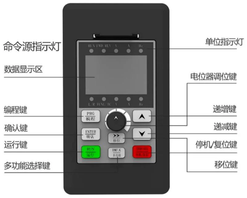
Command source indicator light, unit indicator light, RENIND LV, data display area, potentiometer adjustment key, programming key (PRG), increment key, confirm key (ENTER), decrement key, run key, stop/reset key, multi-function selection key, shift key.
- Function indicator description:
- RUN: When the light is off, it means the frequency converter is in stop state; when the light is on, it means the frequency converter is in running state.
- LOCAL/REMOT: Keyboard operation, terminal operation and remote operation (communication control) indicator lights:
| LOCAL/REMOT status | Start-stop control mode |
|---|---|
| Off | Panel start-stop control mode |
| On | Terminal start-stop control mode |
| Flashing | Communication start-stop control mode |
- FWD/REV: Forward/reverse indicator, the light is on when in forward rotation state.
- TUNE/TC: Tuning/torque control/fault indicator, the light is on when in torque control mode, slow flashing when in tuning state, fast flashing when in fault state.
- Unit indicator lights: Hz (frequency unit), A (current unit), V (voltage unit), RPM(Hz + A) (speed unit), % (A + V) (percentage).
- Digital display area: 5-digit LED display, can display set frequency, output frequency, various monitoring data and alarm codes, etc.
- Keyboard button description table:
Button Name Function PRG Programming key Enter or exit first-level menu ENTER Confirm key Enter menu screen level by level, confirm parameter setting △ Increment key Increment of data or function code ▽ Decrement key Decrement of data or function code ▽ Shift key In stop display interface and running display interface, you can cycle to select display parameters; when modifying parameters, you can select the modification bit of parameters RUN Run key Used for run operation in keyboard operation mode STOP/RES Stop/reset When in running state, press this key to stop running; when in fault alarm state, it can be used for reset operation, the characteristics of this key are restricted by function code P7 - 02 MF.K Multi-function selection key Switch selection according to P7 - 01 function QUICK Menu mode selection key Switch different menu modes according to the value in PP - 03 (default is one menu mode)
8. Basic Function Parameter Table of Inverter
Symbol Description
When PP-00 is set to a non-zero value, that is, a parameter protection password is set. In the function parameter mode and user change parameter mode, the parameter menu must be entered after correct password input. To cancel the password, set PP-00 to 0.
The parameter menu in user customized parameter mode is not password protected.
Group P and Group A are basic function parameters, and Group U is monitoring function parameters. Symbol description in the function table is as follows:
| Symbol | Description |
|---|---|
| “☆” | Indicates that the setting value of this parameter can be changed when the frequency converter is in stop or running state |
| “★” | Indicates that the setting value of this parameter cannot be changed when the frequency converter is in running state |
| “●” | Indicates that the value of this parameter is the actual detection record value and cannot be changed |
| " * " | Indicates that this parameter is a “manufacturer parameter”, which is only set by the manufacturer and is forbidden to be operated by users |
P0 Basic Function Group
| Function code | Name | Setting range | Factory value | Change |
|---|---|---|---|---|
| P0 - 00 | GP type display | 1 : G type (constant torque load model) 2 : P type (fan, pump load model) | Model determined | ● |
| P0 - 01 | First motor control mode | 0 : Sensorless vector control (SVC) 1 : Speed sensor vector control (FVC) 2 : V/F control | 2 | ★ |
| P0 - 02 | Command source selection | 0 : Operation panel command channel (LED off) 1 : Terminal command channel (LED on) 2 : Communication command channel (LED flashing) | 0 | ☆ |
| P0 - 03 | Main frequency source X selection | 0 : Digital setting (preset frequency P0 - 08, UP/DOWN can be modified, power failure not memory) 1 : Digital setting (preset frequency P0 - 08, UP/DOWN can be modified, power failure memory) 2 : AI1 3 : AI2 4 : AI3 5 : PULSE pulse setting (DI5) 6 : Multi-segment command 7 : Simple PLC 8 : PID 9 : Communication given | 0 | ★ |
| P0 - 04 | Auxiliary frequency source Y selection | Same as P0 - 03 (main frequency source X selection) | 0 | ★ |
| P0 - 05 | Overlay auxiliary frequency source Y range selection | 0 : Relative to maximum frequency 1 : Relative to frequency source X | 0 | ☆ |
| P0 - 06 | Overlay auxiliary frequency source Y range | 0% - 150% | 100% | ☆ |
| P0 - 07 | Frequency source overlay mode selection | 0 : Main frequency source X 1 : Main and auxiliary operation results (operation relationship determined by tens digit) 2 : Switch between main frequency source X and auxiliary frequency source Y 3 : Switch between main frequency source X and main and auxiliary operation results 4 : Switch between auxiliary frequency source Y and main and auxiliary operation results Tens digit: main and auxiliary operation relationship of frequency source 0 : main + auxiliary 1 : main - auxiliary 2 : maximum of both 3 : minimum of both | 00 | ☆ |
| P0 - 08 | Preset frequency | 0.00Hz - maximum frequency (P0 - 10) | 50.00Hz | ☆ |
| P0 - 09 | Running direction | 0 : Same direction 1 : Opposite direction | 0 | ☆ |
| P0 - 10 | Maximum frequency | 50.00Hz - 500.00Hz | 50.00Hz | ★ |
| P0 - 11 | Upper frequency source | 0 : P0 - 12 setting 1 : AI1 2 : AI2 3 : AI3 4 : PULSE pulse setting 5 : Communication given | 0 | ★ |
| P0 - 12 | Upper frequency | Lower frequency P0 - 14 - maximum frequency P0 - 10 | 50.00Hz | ☆ |
| P0 - 13 | Upper frequency offset | 0.00Hz - maximum frequency P0 - 10 | 0.00Hz | ☆ |
| P0 - 14 | Lower frequency | 0.00Hz - upper frequency P0 - 12 | 0.00Hz | ☆ |
| P0 - 15 | Carrier frequency | 0.5kHz - 16.0kHz | Model determined | ☆ |
| P0 - 16 | Carrier frequency adjustment with temperature | 0 : No 1 : Yes | 1 | ☆ |
| P0 - 17 | Acceleration time 1 | 0.00s - 65000s | Model determined | ☆ |
| P0 - 18 | Deceleration time 1 | 0.00s - 65000s | Model determined | ☆ |
| P0 - 19 | Acceleration/deceleration time unit | 0 : 1 second 1 : 0.1 second 2 : 0.01 second | 1 | ★ |
| P0 - 22 P0 - 23 | Frequency command resolution Digital setting frequency stop memory selection | 2 : 0.01Hz 0 : No memory 1 : Memory | 2 0 | ★ ☆ |
| P0 - 24 | Motor selection | 0 : Motor 1 1 : Motor 2 1 : Motor 3 3 : Motor 4 | 0 | ★ |
| P0 - 25 | Acceleration/deceleration time reference frequency | 0 : Maximum frequency (P0 - 10) 1 : Set frequency 2 : 100Hz | 0 | ★ |
| P0 - 26 | Frequency command during operation | 0 : Running frequency 1 : Set frequency | 0 | ★ |
| P0 - 27 | Command source binding frequency source | Units digit: Operation panel command binding frequency source selection 0 : No binding 1 : Digital setting frequency 2 : AI1 3 : AI2 4 : AI3 5 : PULSE pulse setting (DI5) 6 : Multi-speed 7 : Simple PLC 8 : PID 9 : Communication given Tens digit: Terminal command binding frequency source selection Hundreds digit: Communication command binding frequency source selection Thousands digit: Automatic operation binding frequency source selection | 0000 | ☆ |
| P0 - 28 | Communication expansion card type | 0 : Modbus communication card 1 : Profibus - DP communication card 2 : CANopen communication card 3 : CANlink communication card | 0 | ☆ |
| P0 - 29 | Application macro | Factory value, then select macro number. Setting range: 0 - 65535 10000 : Function code restore factory setting macro 1 : Variable frequency single pump constant pressure water supply macro 2 : One variable two fixed constant pressure water supply macro (1 variable 2 fixed) 3 : One variable five fixed constant pressure water supply macro (1 variable 4 fixed) 7 : Fire inspection water supply macro 11 : CNC machine tool 100Hz macro 1 12 : CNC machine tool 100Hz macro 2 21 : Spindle engraving 400Hz macro 1 22 : Spindle engraving 400Hz macro 2 Note 1 : Before selecting macro number, execute P0 - 29 restore | 0 | ☆ |
P1 First Motor Parameters
| Function code | Name | Setting range | Factory value | Change |
|---|---|---|---|---|
| P1 - 00 | Motor type selection | 0 : Ordinary asynchronous motor 1 : Frequency conversion asynchronous motor 2 : Permanent magnet synchronous motor | 0 | ★ |
| P1 - 01 | Motor rated power | 0.1kW - 1000.0kW | Model determined | ★ |
| P1 - 02 | Motor rated voltage | 1V - 2000V | Model determined | ★ |
| P1 - 03 | Motor rated current | 0.01A - 655.35A (inverter power <=55kW) 0.1A - 6553.5A (inverter power >55kW) | Model determined | ★ |
| P1 - 04 | Motor rated frequency | 0.01Hz - maximum frequency | Model determined | ★ |
| P1 - 05 | Motor rated speed | 1rpm - 65535rpm | Model determined | ★ |
| P1 - 06 | Asynchronous motor stator resistance | 0.001Ω - 65.535Ω (inverter power <=55kW) 0.0001Ω - 6.5535Ω (inverter power >55kW) | Tuning parameter | ★ |
| P1 - 07 | Asynchronous motor rotor resistance | 0.001Ω - 65.535Ω (inverter power <=55kW) 0.0001Ω - 6.5535Ω (inverter power >55kW) | Tuning parameter | ★ |
| P1 - 08 | Asynchronous motor leakage inductance | 0.01mH - 655.35mH (inverter power <=55kW) 0.001mH - 655.35mH (inverter power >55kW) | Tuning parameter | ★ |
| P1 - 09 | Asynchronous motor mutual inductance | 0.1mH - 6553.5mH (inverter power <=55kW) 0.01mH - 6553.5mH (inverter power >55kW) | Tuning parameter | ★ |
| P1 - 10 | Asynchronous motor no-load current | 0.01A - P1 - 03 (inverter power <=55kW) 0.1A - P1 - 03 (inverter power >55kW) | Tuning parameter | ★ |
| P1 - 16 | Synchronous motor stator resistance | 0.001Ω - 65.535Ω (inverter power <=55kW) 0.0001Ω - 6.5535Ω (inverter power >55kW) | Tuning parameter | ★ |
| P1 - 17 | Synchronous motor D-axis inductance | 0.01mH - 655.35mH (inverter power <=55kW) 0.001mH - 655.35mH (inverter power >55kW) | Tuning parameter | ★ |
| P1 - 18 | Synchronous motor Q-axis inductance | 0.01mH - 655.35mH (inverter power <=55kW) 0.001mH - 655.35mH (inverter power >55kW) | Tuning parameter | ★ |
| P1 - 20 | Synchronous motor back EMF | 0.1V - 6553.5V | Tuning parameter | ★ |
| P1 - 27 | Encoder line count | 1 - 65535 | 2500 | ★ |
| P1 - 28 | Encoder type | 0 : ABZ incremental encoder 1 : UVW incremental encoder 2 : Resolver 3 : Sin cos encoder 4 : Wire-saving UVW encoder | 0 | ★ |
| P1 - 30 | ABZ incremental encoder AB phase sequence | 0 : Forward 1 : Reverse | 0 | ★ |
| P1 - 31 | Encoder installation angle | 0.0 - 359.9° | 0.0° | ★ |
| P1 - 32 | UVW encoder UVW phase sequence | 0 : Forward 1 : Reverse | 0 | ★ |
| P1 - 33 | UVW encoder offset angle | 0.0 - 359.9° | 0.0° | ★ |
| P1 - 34 | Resolver pole pairs | 1 - 65535 | 1 | ★ |
| P1 - 36 | Speed feedback PG disconnection detection time | 0.0 : No action 0.1s - 10.0s | 0.0 | ★ |
| P1 - 37 | Tuning selection | 0 : No operation 1 : Asynchronous motor static tuning 2 : Asynchronous motor complete tuning 11 : Synchronous motor static tuning 12 : Synchronous motor complete tuning | 0 | ★ |
P2 Group First Motor Vector Control Parameters
| Function code | Name | Setting range | Factory value | Change |
|---|---|---|---|---|
| P2 - 00 | Speed loop proportional gain 1 | 1 - 100 | 30 | ☆ |
| P2 - 01 | Speed loop integral time 1 | 0.01s - 10.00s | 0.50s | ☆ |
| P2 - 02 | Switching frequency 1 | 0.00 - P2 - 05 | 5.00Hz | ☆ |
| P2 - 03 | Speed loop proportional gain 2 | 1 - 100 | 20 | ☆ |
| P2 - 04 | Speed loop integral time 2 | 0.01s - 10.00s | 1.00s | ☆ |
| P2 - 05 | Switching frequency 2 | P2 - 02 - maximum frequency | 10.00Hz | ☆ |
| P2 - 06 | Vector control slip gain | 50% - 200% | 150% | ☆ |
| P2 - 07 | Speed loop filter time constant | 0.000s - 0.100s | 0.000s | ☆ |
| P2 - 08 | Vector control overexcitation gain | 0 - 200 | 64 | ☆ |
| P2 - 09 | Torque upper limit source in speed control mode | 0 : Function code P2 - 10 setting 1 : AI1 2 : AI2 3 : AI3 4 : PULSE pulse setting 5 : Communication given 6 : MIN(AI1,AI2) 7 : MAX(AI1,AI2) 1 - 7 options full scale corresponds to P2 - 10 | 0 | ☆ |
| P2 - 10 | Torque upper limit digital setting in speed control mode | 0.0% - 200.0% | 150.0% | ☆ |
| P2 - 13 | Excitation adjustment proportional gain | 0 - 60000 | 2000 | ☆ |
| P2 - 14 | Excitation adjustment integral gain | 0 - 60000 | 1300 | ☆ |
| P2 - 15 | Torque adjustment proportional gain | 0 - 60000 | 2000 | ☆ |
| P2 - 16 | Torque adjustment integral gain | 0 - 60000 | 1300 | ☆ |
| P2 - 17 | Speed loop integral attribute | Units digit: Integral separation 0 : Invalid 1 : Valid | 0 | ☆ |
| P2 - 18 | Synchronous motor weak magnetic mode | 0: Weak magnetic invalid 1: Direct calculation mode 2: Automatic adjustment mode | 1 | ☆ |
| P2 - 19 | Synchronous motor weak magnetic depth | 50% - 500% | 100% | ☆ |
| P2 - 20 | Maximum weak magnetic current | 1% - 300% | 50% | ☆ |
| P2 - 21 | Weak magnetic automatic adjustment gain | 10% - | ||
| P2 - 22 | Weak magnetic integral multiple | 2 - 10 | 2 | ☆ |
P3 Group V/F Control Parameters
| Function code | Name | Setting range | Factory value | Change |
|---|---|---|---|---|
| P3 - 00 | VF curve setting | 0 : Linear V/F 1 : Multi-point V/F 2 : Square V/F 3 : 1.2 power V/F 4 : 1.4 power V/F 6 : 1.6 power V/F 8 : 1.8 power V/F 9 : Reserved 10 : VF fully separated mode 11 : VF semi-separated mode | 0 | ★ |
| P3 - 01 | Torque boost | 0.1% - 30.0% | Model determined | ☆ |
| P3 - 02 | Torque boost cutoff frequency | 0.00Hz - maximum frequency | 50.00Hz | ★ |
| P3 - 03 | Multi-point VF frequency point 1 | 0.00Hz - P3 - 05 | 0.00Hz | ★ |
| P3 - 04 | Multi-point VF voltage point 1 | 0.0% - 100.0% | 0.0% | ★ |
| P3 - 05 | Multi-point VF frequency point 2 | P3 - 03 - P3 - 07 | 0.00Hz | ★ |
| P3 - 06 | Multi-point VF voltage point 2 | 0.0% - 100.0% | 0.0% | ★ |
| P3 - 07 | Multi-point VF frequency point 3 | P3 - 05 - motor rated frequency (P1 - 04) | 0.00Hz | ★ |
| P3 - 08 | Multi-point VF voltage point 3 | 0.0% - 100.0% | 0.0% | ★ |
| P3 - 09 | VF slip compensation gain | 0.0% - 200.0% | 0.0% | ☆ |
| P3 - 10 | VF overexcitation gain | 0 - 200 | 64 | ☆ |
| P3 - 11 | VF oscillation suppression gain | 0 - 100 | Model determined | ☆ |
| P3 - 13 | VF separated voltage source | 0 : Digital setting (P3 - 14) 1 : AI1 2 : AI2 3 : AI3 4 : PULSE pulse setting (DI5) 5 : Multi-segment command 6 : Simple PLC 7 : PID 8 : Communication given Note: 100.0% corresponds to motor rated voltage | 0 | ☆ |
| P3 - 14 | VF separated voltage digital setting | 0V - motor rated voltage | 0V | ☆ |
| P3 - 15 | VF separated voltage rise time | 0.0s - 1000.0s represents time from 0V to rated voltage | 0.0s | ☆ |
P4 Group Input Terminals
| Function code | Name | Setting range | Factory value | Change |
|---|---|---|---|---|
| P4-00 | DI1 terminal function selection | 0 : No function 1 : Forward operation ( FWD ) 2 : Reverse operation ( REV ) 3 : Three-wire operation control 4 : Forward jog ( FJOG ) | 1 | ★ |
| P4-01 | DI2 terminal function selection | 5 : Reverse jog ( RJOG ) 6 : Terminal UP 7 : Terminal DOWN 8 : Free stop 9 : Fault reset ( RESET ) 10 : Run pause | 2 | ★ |
| P4-02 | DI3 terminal function selection | 11 : External fault normally open input 12 : Multi-segment command terminal 1 13 : Multi-segment command terminal 2 14 : Multi-segment command terminal 3 15 : Multi-segment command terminal 4 16 : Acceleration/deceleration time selection terminal 1 | 4 | ★ |
| P4-03 | DI4 terminal function selection | 17 : Acceleration/deceleration time selection terminal 2 18 : Frequency source switching 19 : UP/DOWN setting clear (terminal、keyboard) 20 : Run command switching terminal 1 21 : Acceleration/deceleration prohibition | 9 | ★ |
| P4-04 | DI5 terminal function selection | 22 : PID pause 23 : PLC state reset 24 : Swing frequency pause 25 : Counter input 26 : Counter reset 27 : Length counting input | 12 | ★ |
| P4-05 | DI6 terminal function selection | 28 : Length reset 29 : Torque control prohibition 30 : PULSE (pulse) frequency input 31 : Reserved 32 : Immediate DC braking (only valid for DI5) | 0 | ★ |
| P4-06 | DI7 terminal function selection | 33 : External fault normally closed input 34 : Frequency modification enable 35 : PID action direction inversion 36 : External stop terminal 1 37 : Run command switching terminal 2 38 : PID integral pause | 0 | ★ |
| P4-07 | DI8 terminal function selection | 39 : Frequency source X and preset frequency switching 40 : Frequency source Y and preset frequency switching 41 : Motor selection terminal 1 42 : Motor selection terminal 2 43 : PID parameter switching | 0 | ★ |
| P4-08 | DI9 terminal function selection | 44:User-defined fault 1 45 : User-defined fault 2 46 : Speed control / torque control switching 47 : Emergency stop 48 : External stop terminal 2 49 : Deceleration DC braking 50 : Clear current running time 51-59 : Reserved | 0 | ★ |
| P4-09 | DI10 terminal function selection | 0 | ★ | |
| P4-10 | DI filter time | 0.000s - 1.000s | 0.010s | ☆ |
| P4-11 | Terminal command mode | 0 : Two-wire type 1 1 : Two-wire type 2 2 : Three-wire type 1 3 : Three-wire type 2 | 0 | ★ |
| P4-12 | Terminal UP/DOWN change rate | 0.001Hz/s - 65.535Hz/s | 1.00Hz/s | ☆ |
| P4-13 | AI curve 1 minimum input | 0.00V - P4-15 | 0.00V | ☆ |
| P4-14 | AI curve 1 minimum input corresponding setting | -100.0% - +100.0% | 0.0% | ☆ |
| P4-15 | AI curve 1 maximum input | P4-13 - +10.00V | 10.00V | ☆ |
| P4-16 | AI curve 1 maximum input corresponding setting | -100.0% - +100.0% | 100.0% | ☆ |
| P4-17 | AI1 filter time | 0.00s - 10.00s | 0.10s | ☆ |
| P4-18 | AI curve 2 minimum input | 0.00V - P4-20 | 0.00V | ☆ |
| P4-19 | AI curve 2 minimum input corresponding setting | -100.0% - +100.0% | 0.0% | ☆ |
| P4-20 | AI curve 2 maximum input | P4-18 - +10.00V | 10.00V | ☆ |
| P4-21 | AI curve 2 maximum input corresponding setting | -100.0% - +100.0% | 100.0% | ☆ |
| P4-22 | AI2 filter time | 0.00s - 10.00s | 0.10s | ☆ |
| P4-23 | AI curve 3 minimum input | -10.00V - P4-25 | 0.1V | ☆ |
| P4-24 | AI curve 3 minimum input corresponding setting | -100.0% - +100.0% | 0 | ☆ |
| P4-25 | AI curve 3 maximum input | P4-23 - +10.00V | 4.00V | ☆ |
| P4-26 | AI curve 3 maximum input corresponding setting | -100.0% - +100.0% | 100.0% | ☆ |
| P4-27 | AI3 filter time | 0.00s - 10.00s | 0.10s | ☆ |
| P4-28 | PULSE minimum input | 0.00kHz - P4-30 | 0.00kHz | ☆ |
| P4-29 | PULSE minimum input corresponding setting | -100.0% - 100.0% | 0.0% | ☆ |
| P4-30 | PULSE maximum input | P4-28 - 100.00kHz | 50.00kHz | ☆ |
| P4-31 | PULSE maximum input setting | -100.0% - 100.0% | 100.0% | ☆ |
| P4-32 | PULSE filter time | 0.00s - 10.00s | 0.10s | ☆ |
| P4-33 | AI curve selection | Units digit: AI1 curve selection 1 : Curve 1(2 points, see P4-13 - P4-16) 2 : Curve 2(2 points, see P4-18 - P4-21) 3 : Curve 3(2 points, see P4-23 - P4-26) 4 : Curve 4(4 points, see A6-00 - A6-07) 5 : Curve 5(4 points, see A6-08 - A6-15) Tens digit: AI2 curve selection, same as above Hundreds digit: AI3 curve selection, same as above | 321 | ☆ |
| P4-34 | AI below minimum input setting selection | Units digit: AI1 below minimum input setting selection 0 : Corresponding to minimum input setting 1 : 0.0% Tens digit: AI2 below minimum input setting selection, same as above Hundreds digit: AI3 below minimum input setting selection, same as above | 000 | ☆ |
| P4-35 | DI1 delay time | 0.0s - 3600.0s | 0.0s | ★ |
| P4-36 | DI2 delay time | 0.0s - 3600.0s | 0.0s | ★ |
| P4-37 | DI3 delay time | 0.0s - 3600.0s | 0.0s | ★ |
| P4-38 | DI terminal effective mode selection 1 | 0 : High level effective 1 : Low level effective Units digit: DI1 Tens digit: DI2 Hundreds digit: DI3 Thousands digit: DI4 Ten thousands digit: DI5 | 00000 | ★ |
| P4-39 | DI terminal effective mode selection 2 | 0 : High level effective 1 : Low level effective Units digit: DI6 Tens digit: DI7 Hundreds digit: DI8 Thousands digit: DI9 Ten thousands digit: DI10 | 00000 | ★ |
P5 Group Output Terminals
| Function code | Name | Setting range | Factory value | Change |
|---|---|---|---|---|
| P5-00 | FM terminal output mode selection | 0 : Pulse output(FMP) 1 : Switch output(FMR) | 0 | ☆ |
| P5-01 | FMR output function selection | 0 : No output 1 : Inverter running 2 : Fault output(fault shutdown) 3 : Frequency level detection FDT1 output 4 : Frequency arrival 5 : Zero speed running(not output when stopped) 6 : Motor overload pre-alarm 7 : Inverter overload pre-alarm 8 : Set count value reached 9 : Length reached 10 : Simple PLC phase completed 11 : Torque limiting 12 : Running ready 13 : AI1>AI2 14 : Upper limit frequency reached 15 : Lower limit frequency reached(related to running) 16 : Undervoltage state output 17 : Communication setting 18 : Positioning completed(reserved) 19 : Positioning approaching(reserved) 20 : Zero speed running 2(output when stopped) 21 : Cumulative power-on time reached 22 : Frequency level detection FDT2 output 23 : Frequency 1 arrival output 24 : Frequency 2 arrival output 25 : Current 1 arrival output 26 : Current 2 arrival output 27 : Timing arrival output 28 : AI1 input over-limit 29 : Load loss 30 : Reverse running 31 : Zero current state 32 : Module temperature reached 33 : Output current over-limit 34 : Lower limit frequency reached(output when stopped) 35 : Alarm output(continue running) 36 : Motor overheating pre-alarm 37 : Current running time reached | 0 | ☆ |
| P5-02 | Control board relay function selection (T/A - T/B - T/C) | Same as P5-01 options | 2 | ☆ |
| P5-03 | Expansion card relay output function selection (P/A - P/B - P/C) | Same as P5-01 options | 0 | ☆ |
| P5-04 | DO1 output function selection | Same as P5-01 options | 1 | ☆ |
| P5-05 | Expansion card DO2 output selection | Same as P5-01 options | 4 | ☆ |
| P5-06 | FMP output function selection | 0 : Running frequency 1 : Set frequency 2 : Output current 3 : Output torque 4 : Output power 5 : Output voltage 6 : PULSE input 7 : AI1 8 : AI2 9 : AI3(expansion card) 10 : Length 11 : Count value 12 : Communication setting 13 : Motor speed 14 : Output current(100.0% corresponds to 1000.0A) 15 : Output voltage(100.0% corresponds to 1000.0V) 16 : Reserved(100.% corresponds to 100.0kHz) | 0 | ☆ |
| P5-07 | AO1 output function selection | Same as P5-06 options | 0 | ☆ |
| P5-08 | Expansion card AO2 output function selection | Same as P5-06 options | 1 | ☆ |
| P5-09 | FMP output maximum frequency | 0.01kHz - 100.00kHz | 50.00kHz | ☆ |
| P5-10 | AO1 zero offset coefficient | -100.0% - +100.0% | 0.0% | ☆ |
| P5-11 | AO1 gain | -10.00 - +10.00 | 1.00 | ☆ |
| P5-12 | Expansion card AO2 zero offset coefficient | -100.0% - +100.0% | 0.0% | ☆ |
| P5-13 | Expansion card AO2 gain | -10.00 - +10.00 | 1.00 | ☆ |
| P5-17 | FMR output delay time | 0.0s - 3600.0s | 0.0s | ☆ |
| P5-18 | RELAY1 output delay time | 0.0s - 3600.0s | 0.0s | ☆ |
| P5-20 | DO1 output delay time | 0.0s - 3600.0s | 0.0s | ☆ |
| P5-21 | DO2 output delay time | 0.0s - 3600.0s | 0.0s | ☆ |
| P5-22 | DO output terminal effective state selection | 0 : Positive logic 1 : Negative logic Units digit: FMR Tens digit: RELAY1 Hundreds digit: RELAY2 Thousands digit: DO1 Ten thousands digit: DO2 | 00000 | ☆ |
P6 Group Start/Stop Control
| Function code | Name | Setting range | Factory value | Change |
|---|---|---|---|---|
| P6-00 | Start mode | 0 : Direct start 1 : Speed tracking restart 2 : Pre-excitation start(AC asynchronous motor) | 0 | ☆ |
| P6-01 | Speed tracking mode | 0 : Start from stop frequency 1 : Start from zero speed 2 : Start from maximum frequency | 0 | ★ |
| P6-02 | Speed tracking speed | 1 - 100 | 20 | ☆ |
| P6-03 | Start frequency | 0.00Hz - 10.00Hz | 0.00Hz | ☆ |
| P6-04 | Start frequency hold time | 0.0s-100.0s | 0.0s | ★ |
| P6-05 | Start DC braking current/pre-excitation current | 0%-100% | 0% | ★ |
| P6-06 | Start DC braking time/pre-excitation time | 0.0s-100.0s | 0.0s | ★ |
| P6-07 | Acceleration mode | 0:Linear acceleration 1:S-curve acceleration A 2:S-curve acceleration B | - | ★ |
| P6-08 | S-curve start time ratio | 0.0%-(100.0%-P6-09) | 30.0% | ★ |
| P6-09 | S-curve end time ratio | 0.0%-(100.0%-P6-08) | 30.0% | ★ |
| P6-10 | Stop mode | 0:Deceleration stop 1:Free stop | - | ☆ |
| P6-11 | Stop DC braking start frequency | 0.0Hz-maximum frequency | 0.00Hz | ☆ |
| P6-12 | Stop DC braking wait time | 0.0s-100.0s | 0.0s | ☆ |
| P6-13 | Stop DC braking current | 0%-100% | 0% | ☆ |
| P6-14 | Stop DC braking time | 0.0s-100.0s | 0.0s | ☆ |
| P6-15 | Braking usage rate | 0%-100% | 100% | ☆ |
P7 Group Keyboard and Display
| Function code | Name | Setting range | Factory value | Change |
|---|---|---|---|---|
| P7-00 | Display function extension 1 Units digit: Power voltage monitoring mode 0 : DC bus voltage 1 : Input AC voltage(preceded by U letter) | - | 00000 | ☆ |
| P7-01 | MF.K key function selection 0 : MF.K disabled 1 : Switch between operation panel command channel and remote command channel (terminal command channel or communication command channel) 2 : Forward/reverse rotation switch 3 : Forward jog 4 : Reverse jog | - | 3 | ★ |
| P7-02 | STOP/RESET key function 0 : STOP/RES key stop function is only effective in keyboard operation mode 1 : STOP/RES key stop function is effective in any operation mode | - | 1 | ☆ |
| P7-03 | LED running display parameter 1 0000~FFFF Bit00: Running frequency 1 (Hz) Bit01: Set frequency (Hz) Bit02: Bus voltage (V) Bit03: Output voltage (V) Bit04: Output current (A) Bit05: Output power (kW) Bit06: Output torque (%) Bit07: DI input status Bit08: DO output status Bit09: AI1 voltage (V) Bit10: AI2 voltage (V) Bit11: AI3 voltage (V) Bit12: Count value Bit13: Length value Bit14: Load speed display Bit15: PID setting | 0000~FFFF | 1F | ☆ |
| P7-04 | LED running display parameter 2 0000~FFFF Bit00:PID feedback Bit01:PLC phase Bit02:PULSE input pulse frequency (kHz) Bit03:Running frequency 2 (Hz) Bit04:Remaining running time Bit05:AI1 voltage before correction (V) Bit06:AI2 voltage before correction (V) Bit07:AI3 voltage before correction (V) Bit08:Linear speed Bit09:Current power-on time (Hour) Bit10:Current running time (Min) Bit11:PULSE input pulse frequency (Hz) Bit12:Communication set value Bit13:Encoder feedback speed (Hz) Bit14:Main frequency X display (Hz) Bit15:Auxiliary frequency Y display (Hz) | 0000~FFFF | 0000 | ☆ |
| P7-05 | LED stop display parameter 0000~FFFF Bit00: Set frequency (Hz) Bit01: Bus voltage (V) Bit02: DI input status Bit03: DO output status Bit04: AI1 voltage (V) Bit05: AI2 voltage (V) Bit06: AI3 voltage (V) Bit07: Count value Bit08: Length value Bit09: PLC phase Bit10: Load speed Bit11: PID setting Bit12:PULSE input pulse frequency (kHz) | 0000~FFFF | 0033 | ☆ |
| P7-06 | Load speed display coefficient | 0.0001~6.5000 | 1.0000 | ☆ |
| P7-07 | Inverter module heatsink temperature | 0.0℃~100.0℃ | - | ● |
| P7-08 | Rectifier bridge heatsink temperature | 0.0℃~100.0℃ | - | ● |
| P7-09 | Accumulated running time | 0h~65535h | - | ● |
| P7-10 | Product number | - | - | ● |
| P7-11 | Software version number | - | - | ● |
| P7-12 | Load speed display decimal places 0 : 0 decimal places 1 : 1 decimal place 2 : 2 decimal places 3 : 3 decimal places | - | 1 | ☆ |
| P7-13 | Accumulated power-on time | 0h~65535h | - | ● |
| P7-14 | Accumulated power consumption | 0kW~65535 kWh | - | ● |
| P7-17 | Digital tube 2 stop monitoring selection | 0000~FFFF | 0000 | ☆ |
| P7-18 | Digital tube 2 running monitoring selection | 0000~FFFF | 0000 | ☆ |
P8 Group Auxiliary Functions
| Function code | Name | Setting range | Factory value | Change |
|---|---|---|---|---|
| P8-00 | Jog running frequency | 0.00Hz~maximum frequency | 6.00Hz | ☆ |
| P8-01 | Jog acceleration time | 0.0s~6500.0s | 20.0s | ☆ |
| P8-02 | Jog deceleration time | 0.0s~6500.0s | 20.0s | ☆ |
| P8-03 | Acceleration time 2 | 0.0s~6500.0s | Machine default | ☆ |
| P8-04 | Deceleration time 2 | 0.0s~6500.0s | Machine default | ☆ |
| P8-05 | Acceleration time 3 | 0.0s~6500.0s | Machine default | ☆ |
| P8-06 | Deceleration time 3 | 0.0s~6500.0s | Machine default | ☆ |
| P8-07 | Acceleration time 4 | 0.0s~6500.0s | Machine default | ☆ |
| P8-08 | Deceleration time 4 | 0.0s~6500.0s | Machine default | ☆ |
| P8-09 | Skip frequency 1 | 0.00Hz~maximum frequency | 0.00Hz | ☆ |
| P8-10 | Skip frequency 2 | 0.00Hz~maximum frequency | 0.00Hz | ☆ |
| P8-11 | Skip frequency amplitude | 0.00Hz~maximum frequency | 0.01Hz | ☆ |
| P8-12 | Forward/reverse dead time | 0.0s~3000.0s | 0.0s | ☆ |
| P8-13 | Reverse control enable | 0:Allow 1:Prohibit | 0 | ☆ |
| P8-14 | Operation mode when set frequency is lower than lower limit frequency | 0:Run at lower limit frequency 1:Stop 2:Zero speed operation | 0 | ☆ |
| P8-15 | Droop control | 0.00Hz~10.00Hz | 0.00Hz | ☆ |
| P8-16 | Set accumulated power-on arrival time | 0h~65000h | 0h | ☆ |
| P8-17 | Set accumulated running arrival time | 0h~65000h | 0h | ☆ |
| P8-18 | Start protection selection | 0:No protection 1:Protection | 0 | ☆ |
| P8-19 | Frequency detection value (FDT1) | 0.00Hz~maximum frequency | 50.00Hz | ☆ |
| P8-20 | Frequency detection hysteresis value (FDT1) | 0.0%~100.0% (FDT1 level) | 5.0% | ☆ |
| P8-21 | Frequency arrival detection width | 0.0%~100.0% (maximum frequency) | 0.0% | ☆ |
| P8-22 | Whether skip frequency is effective during acceleration/deceleration | 0:Ineffective 1:Effective | 0 | ☆ |
| P8-25 | Switching frequency point between acceleration time 1 and acceleration time 2 | 0.00Hz~maximum frequency | 0.00Hz | ☆ |
| P8-26 | Switching frequency point between deceleration time 1 and deceleration time 2 | 0.00Hz~maximum frequency | 0.00Hz | ☆ |
| P8-27 | Terminal jog priority | 0:Ineffective 1:Effective | 0 | ☆ |
| P8-28 | Frequency detection value (FDT2) | 0.00Hz~maximum frequency | 50.00Hz | ☆ |
| P8-29 | Frequency detection hysteresis value (FDT2) | 0.0%~100.0% (FDT2 level) | 5.0% | ☆ |
| P8-30 | Arbitrary arrival frequency detection value 1 | 0.00Hz~maximum frequency | 50.00Hz | ☆ |
| P8-31 | Arbitrary arrival frequency detection width 1 | 0.0%~100.0% (maximum frequency) | 0.0% | ☆ |
| P8-32 | Arbitrary arrival frequency detection value 2 | 0.00Hz~maximum frequency | 50.00Hz | ☆ |
| P8-33 | Arbitrary arrival frequency detection width 2 | 0.0%~100.0% (maximum frequency) | 0.0% | ☆ |
| P8-34 | Zero current detection level | 0.0%~300.0% (100.0% corresponds to motor rated current) | 5.0% | ☆ |
| P8-35 | Zero current detection delay time | 0.01s~600.00s | 0.10s | ☆ |
| P8-36 | Output current over-limit value | 0.0%(no detection) 0.1%~300.0%(motor rated current) | 200.0% | ☆ |
| P8-37 | Output current over-limit detection delay time | 0.00s~600.00s | 0.00s | ☆ |
| P8-38 | Arbitrary arrival current 1 | 0.0%~300.0%(motor rated current) | 100.0% | ☆ |
| P8-39 | Arbitrary arrival current 1 width | 0.0%~300.0%(motor rated current) | 0.0% | ☆ |
| P8-40 | Arbitrary arrival current 2 | 0.0%~300.0%(motor rated current) | 100.0% | ☆ |
| P8-41 | Arbitrary arrival current 2 width | 0.0%~300.0%(motor rated current) | 0.0% | ☆ |
| P8-42 | Timing function selection | 0:Ineffective 1:Effective | 0 | ☆ |
| P8-43 | Timing running time selection | 0:P8-44 setting 1:AI1 2:AI2 3:AI3(analog input range corresponds to P8-44) | 0 | ☆ |
| P8-44 | Timing running time | 0.0Min~6500.0Min | 0.0Min | ☆ |
| P8-45 | AI1 input voltage protection value lower limit | 0.00V~P8-46 | 3.10V | ☆ |
| P8-46 | AI1 input voltage protection value upper limit | P8-45~10.00V | 6.80V | ☆ |
| P8-47 | Module temperature arrival | 0℃~100℃ | 75℃ | ☆ |
| P8-48 | Cooling fan control | 0:Fan runs when running 1:Fan always runs | 0 | ☆ |
| P8-49 | Wake-up frequency | Sleep frequency (P8-51)~maximum frequency (P0-10) | 0.00Hz | ☆ |
| P8-50 | Wake-up delay time | 0.0s~6500.0s | 0.0s | ☆ |
| P8-51 | Sleep frequency | 0.00Hz~wake-up frequency (P8-49) | 0.00Hz | ☆ |
| P8-52 | Sleep delay time | 0.0s~6500.0s | 0.0s | ☆ |
| P8-53 | This running arrival time setting | 0.0Min~6500.0Min | 0.0Min | ☆ |
P9 Group Fault and Protection
| Function code | Name | Setting range | Factory value | Change |
|---|---|---|---|---|
| P9-00 | Motor overload protection selection | 0:Prohibit 1:Allow | 1 | ☆ |
| P9-01 | Motor overload protection gain | 0.20~10.00 | 1.00 | ☆ |
| P9-02 | Motor overload pre-alarm coefficient | 50%~100% | 80% | ☆ |
| P9-03 | Overvoltage stall gain | 0~100 | 0 | ☆ |
| P9-04 | Overvoltage stall protection voltage | 120%~150% | 130% | ☆ |
| P9-05 | Overcurrent stall gain | 0~100 | 20 | ☆ |
| P9-06 | Overcurrent stall protection current | 100%~200% | 150% | ☆ |
| P9-07 | Power-on ground fault protection selection | 0:Ineffective 1:Effective | 1 | ☆ |
| P9-09 | Fault automatic reset times | 0~20 | 0 | ☆ |
| P9-10 | Fault DO action selection during fault automatic reset period | 0:No action 1:Action | 0 | ☆ |
| P9-11 | Fault automatic reset interval time | 0.1s~100.0s | 1.0s | ☆ |
| P9-12 | Input phase loss and contactor protection selection | 0:Prohibit 1:Allow | 1 | ☆ |
| P9-13 | Output phase loss protection selection | 0:Prohibit 1:Allow | 1 | ☆ |
| P9-14 | First fault type | 0:No fault 1:Reserved 2:Acceleration overcurrent 3:Deceleration overcurrent 4:Constant speed overcurrent 5:Acceleration overvoltage 6:Deceleration overvoltage 7:Constant speed overvoltage 8:Buffer resistor overload 9:Undervoltage 10:Inverter overload 11:Motor overload 12:Input phase loss 13:Output phase loss 14:Module overheating 15:External fault 16:Communication abnormality 17:Contactor abnormality 18:Current detection abnormality 19:Motor tuning abnormality 20:Encoder/PG card abnormality 21:Parameter read/write abnormality 22:Inverter hardware abnormality 23:Motor ground fault 24:Reserved 25:Reserved 26:Running time arrived 27: User-defined fault 1 28: User-defined fault 2 29: Power-on time arrived 30:Load loss 31:Running PID feedback loss 40:Fast current limiting timeout 41:Motor switching during operation 42: Speed deviation too large 43:Motor overspeed 45:Motor overheating 51:Initial position error | - | ● |
| P9-15 | Second fault type | - | - | ● |
| P9-16 | Third (latest) fault type | - | - | ● |
| P9-17 | Third (latest) fault frequency | - | - | ● |
| P9-18 | Third (latest) fault current | - | - | ● |
| P9-19 | Third (latest) fault bus voltage | - | - | ● |
| P9-20 | Third (latest) fault input terminal status | - | - | ● |
| P9-21 | Third (latest) fault output terminal status | - | - | ● |
| P9-22 | Third (latest) fault inverter status | - | - | ● |
| P9-23 | Third (latest) fault power-on time | - | - | ● |
| P9-24 | Third (latest) fault running time | - | - | ● |
| P9-27 | Second fault frequency | - | - | ● |
| P9-28 | Second fault current | - | - | ● |
| P9-29 | Second fault bus voltage | - | - | ● |
| P9-30 | Second fault input terminal status | - | - | ● |
| P9-31 | Second fault output terminal status | - | - | ● |
| P9-32 | Second fault inverter status | - | - | ● |
| P9-33 | Second fault power-on time | - | - | ● |
| P9-34 | Second fault running time | - | - | ● |
| P9-37 | First fault frequency | - | - | ● |
| P9-38 | First fault current | - | - | ● |
| P9-39 | First fault bus voltage | - | - | ● |
| P9-40 | First fault input terminal status | - | - | ● |
| P9-41 | First fault output terminal status | - | - | ● |
| P9-42 | First fault inverter status | - | - | ● |
| P9-43 | First fault power-on time | - | - | ● |
| P9-44 | First fault running time | - | - | ● |
| P9-47 | Fault protection action selection 1 | Units digit:Motor overload (11) 0:Free stop 1:Stop according to stop mode 2:Continue running Tens digit:Input phase loss (12) Hundreds digit:Output phase loss (13) Thousands digit:External fault (15) Ten thousands digit:Communication abnormality (16) | 00000 | ☆ |
| P9-48 | Fault protection action selection 2 | Units digit:Encoder/PG card abnormality (20) 0:Free stop Tens digit:Function code read/write abnormality (21) 0:Free stop 1:Stop according to stop mode Hundreds digit:Reserved Thousands digit:Motor overheating (25) Ten thousands digit:Running time arrived (26) | 00000 | ☆ |
| P9-49 | Fault protection action selection 3 | Units digit:User-defined fault 1 (27) 0:Free stop 1:Stop according to stop mode 2:Continue running Tens digit:User-defined fault 2 (28) 0:Free stop 1:Stop according to stop mode 2:Continue running Hundreds digit:Power-on time arrived (29) 0:Free stop 1:Stop according to stop mode 2:Continue running Thousands digit:Load loss (30) 0:Free stop 1:Deceleration stop 2:Decelerate to 7% of motor rated frequency and continue running, automatically recover to set frequency when load is not lost Ten thousands digit:Running PID feedback loss (31) 0:Free stop 1:Stop according to stop mode 2:Continue running | 00000 | ☆ |
| P9-50 | Fault protection action selection 4 | Units digit:Speed deviation too large (42) 0:Free stop 1:Stop according to stop mode 2:Continue running Tens digit:Motor overspeed (43) Hundreds digit:Initial position error (51) | 00000 | ☆ |
| P9-54 | Fault protection continue running frequency selection | 0:Run at current running frequency 1:Run at set frequency 2:Run at upper limit frequency 3:Run at lower limit frequency 4:Run at abnormal standby frequency | 0 | ☆ |
| P9-55 | Abnormal standby frequency | 60.0%~100.0% (100.0% corresponds to maximum frequency P0-10) | 100.0% | ☆ |
| P9-56 | Motor temperature sensor type | 0:No temperature sensor 1:PT100 2:PT1000 | 0 | ☆ |
| P9-57 | Motor overheating protection threshold | 0℃~200℃ | 110℃ | ☆ |
| P9-58 | Motor overheating pre-alarm threshold | 0℃~200℃ | 90℃ | ☆ |
| P9-59 | Instantaneous power failure action selection | 0:Ineffective 1:Deceleration 2:Deceleration stop | 0 | ☆ |
| P9-60 | Instantaneous power failure action pause judgment voltage | P9-62~100.0% | 100.0% | ☆ |
| P9-61 | Instantaneous power failure voltage recovery judgment time | 0.00s~100.00s | 0.50s | ☆ |
| P9-62 | Instantaneous power failure action judgment voltage | 60.0%~100.0% (standard bus voltage) | 80.0% | ☆ |
| P9-63 | Load loss protection selection | 0:Ineffective 1:Effective | 0 | ☆ |
| P9-64 | Load loss detection level | 0.0~100.0% | 10.0% | ☆ |
| P9-65 | Load loss detection time | 0.0~60.0s | 1.0s | ☆ |
| P9-67 | Overspeed detection value | 0.0%~50.0%(maximum frequency) | 20.0% | ☆ |
| P9-68 | Overspeed detection time | 0.0s~60.0s | 1.0s | ☆ |
| P9-69 | Speed deviation too large detection value | 0.0%~50.0%(maximum frequency) | 20.0% | ☆ |
| P9-70 | Speed deviation too large detection time | 0.0s~60.0s | 5.0s | ☆ |
PA Group PID Functions
| Function code | Name | Setting range | Factory value | Change |
|---|---|---|---|---|
| PA-00 | PID setpoint source | 0:PA-01 setting 1:AI1 2:AI2 3:AI3 4:PULSE pulse setting (DI5) 5:Communication given 6:Multi-segment command given 7:Pressure given by water supply group b0-01 | 0 | ☆ |
| PA-01 | PID numerical given | 0.0%~100.0% | 50.0% | ☆ |
| PA-02 | PID feedback source | 0:AI1 1:AI2 2:AI3 3:AI1 - AI2 4:PULSE pulse setting (DI5) 5:Communication given 6:AI1 + AI2 7:MAX( | AI1 | , |
| PA-03 | PID action direction | 0:Positive action 1:Reverse action | 0 | ☆ |
| PA-04 | PID given feedback range | 0~65535 | 1000 | ☆ |
| PA-05 | Proportional gain KP1 | 0.0~100.0 | 20.0 | ☆ |
| PA-06 | Integral time Ti1 | 0.01s~10.00s | 2.00s | ☆ |
| PA-07 | Derivative time Td1 | 0.000s~10.000s | 0.000s | ☆ |
| PA-08 | PID reverse cut-off frequency | 0.00~maximum frequency | 2.00Hz | ☆ |
| PA-09 | PID deviation limit | 0.0%~100.0% | 0.0% | ☆ |
| PA-10 | PID derivative limit | 0.00%~100.00% | 0.10% | ☆ |
| PA-11 | PID given change time | 0.00~650.00s | 0.00s | ☆ |
| PA-12 | PID feedback filtering time | 0.00~60.00s | 0.00s | ☆ |
| PA-13 | PID output filtering time | 0.00~60.00s | 0.00s | ☆ |
| PA-14 | Reserved | - | - | ☆ |
| PA-15 | Proportional gain KP2 | 0.0~100.0 | 20.0 | ☆ |
| PA-16 | Integral time Ti2 | 0.01s~10.00s | 2.00s | ☆ |
| PA-17 | Derivative time Td2 | 0.000s~10.000s | 0.000s | ☆ |
| PA-18 | PID parameter switching condition | 0:No switching 1:Switching through DI terminal 2:Automatic switching according to deviation | 0 | ☆ |
| PA-19 | PID parameter switching deviation 1 | 0.0%~PA-20 | 20.0% | ☆ |
| PA-20 | PID parameter switching deviation 2 | PA-19~100.0% | 80.0% | ☆ |
| PA-21 | PID initial value | 0.0%~100.0% | 0.0% | ☆ |
| PA-22 | PID initial value holding time | 0.00~650.00s | 0.00s | ☆ |
| PA-23 | Forward maximum value of two output deviations | 0.00%~100.00% | 1.00% | ☆ |
| PA-24 | Reverse maximum value of two output deviations | 0.00%~100.00% | 1.00% | ☆ |
| PA-25 | PID integral attribute | Units digit:Integral separation 0:Ineffective 1:Effective Tens digit:Whether to stop integration after output reaches limit 0:Continue integration 1:Stop integration | 00 | ☆ |
| PA-26 | PID feedback loss detection value | 0.0%:Do not judge feedback loss 0.1%~100.0% | 0.0% | ☆ |
| PA-27 | PID feedback loss detection time | 0.0s~20.0s | 0.0s | ☆ |
| PA-28 | PID stop calculation | 0:No calculation when stopped 1:Calculate when stopped | 0 | ☆ |
Pb Group Swing Frequency, Fixed Length and Counting
| Function code | Name | Setting range | Factory value | Change |
|---|---|---|---|---|
| Pb-00 | Swing frequency setting mode | 0:Relative to center frequency 1:Relative to maximum frequency | 0 | ☆ |
| Pb-01 | Swing frequency amplitude | 0.0%~100.0% | 0.0% | ☆ |
| Pb-02 | Jump frequency amplitude | 0.0%~50.0% | 0.0% | ☆ |
| Pb-03 | Swing frequency period | 0.1s~3000.0s | 10.0s | ☆ |
| Pb-04 | Swing frequency triangular wave rise time | 0.1%~100.0% | 50.0% | ☆ |
| Pb-05 | Set length | 0m~65535m | 1000m | ☆ |
| Pb-06 | Actual length | 0m~65535m | 0m | ☆ |
| Pb-07 | Pulses per meter | 0.1~6553.5 | 100.0 | ☆ |
| Pb-08 | Set count value | 1~65535 | 1000 | ☆ |
| Pb-09 | Specified count value | 1~65535 | 1000 | ☆ |
PC Group Multi-segment Commands, Simple PLC
| Function code | Name | Setting range | Factory value | Change |
|---|---|---|---|---|
| PC-00 | Multi-segment command 0 | -100.0%~100.0% | 0.0% | ☆ |
| PC-01 | Multi-segment command 1 | -100.0%~100.0% | 0.0% | ☆ |
| PC-02 | Multi-segment command 2 | -100.0%~100.0% | 0.0% | ☆ |
| PC-03 | Multi-segment command 3 | -100.0%~100.0% | 0.0% | ☆ |
| PC-04 | Multi-segment command 4 | -100.0%~100.0% | 0.0% | ☆ |
| PC-05 | Multi-segment command 5 | -100.0%~100.0% | 0.0% | ☆ |
| PC-06 | Multi-segment command 6 | -100.0%~100.0% | 0.0% | ☆ |
| PC-07 | Multi-segment command 7 | -100.0%~100.0% | 0.0% | ☆ |
| PC-08 | Multi-segment command 8 | -100.0%~100.0% | 0.0% | ☆ |
| PC-09 | Multi-segment command 9 | -100.0%~100.0% | 0.0% | ☆ |
| PC-10 | Multi-segment command 10 | -100.0%~100.0% | 0.0% | ☆ |
| PC-11 | Multi-segment command 11 | -100.0%~100.0% | 0.0% | ☆ |
| PC-12 | Multi-segment command 12 | -100.0%~100.0% | 0.0% | ☆ |
| PC-13 | Multi-segment command 13 | -100.0%~100.0% | 0.0% | ☆ |
| PC-14 | Multi-segment command 14 | -100.0%~100.0% | 0.0% | ☆ |
| PC-15 | Multi-segment command 15 | -100.0%~100.0% | 0.0% | ☆ |
| PC-16 | Simple PLC running mode | 0:Stop after single operation end 1:Hold final value after single operation end 2:Loop continuously | 0 | ☆ |
| PC-17 | Simple PLC power-off memory selection | Units digit:Power-off memory selection 0:No memory after power-off 1:Memory after power-off Tens digit:Stop memory selection 0:No memory after stop 1:Memory after stop | 00 | ☆ |
| PC-18 | Simple PLC segment 0 running time | 0.0s(h)~6553.5s(h) | 0.0s(h) | ☆ |
| PC-19 | Simple PLC segment 0 acceleration/deceleration time selection | 0~3 | 0 | ☆ |
| PC-20 | Simple PLC segment 1 running time | 0.0s(h)~6553.5s(h) | 0.0s(h) | ☆ |
| PC-21 | Simple PLC segment 1 acceleration/deceleration time selection | 0~3 | 0 | ☆ |
| PC-22 | Simple PLC segment 2 running time | 0.0s(h)~6553.5s(h) | 0.0s(h) | ☆ |
| PC-23 | Simple PLC segment 2 acceleration/deceleration time selection | 0~3 | 0 | ☆ |
| PC-24 | Simple PLC segment 3 running time | 0.0s(h)~6553.5s(h) | 0.0s(h) | ☆ |
| PC-25 | Simple PLC segment 3 acceleration/deceleration time selection | 0~3 | 0 | ☆ |
| PC-26 | Simple PLC segment 4 running time | 0.0s(h)~6553.5s(h) | 0.0s(h) | ☆ |
| PC-27 | Simple PLC segment 4 acceleration/deceleration time selection | 0~3 | 0 | ☆ |
| PC-28 | Simple PLC segment 5 running time | 0.0s(h)~6553.5s(h) | 0.0s(h) | ☆ |
| PC-29 | Simple PLC segment 5 acceleration/deceleration time selection | 0~3 | 0 | ☆ |
| PC-30 | Simple PLC segment 6 running time | 0.0s(h)~6553.5s(h) | 0.0s(h) | ☆ |
| PC-31 | Simple PLC segment 6 acceleration/deceleration time selection | 0~3 | 0 | ☆ |
| PC-32 | Simple PLC segment 7 running time | 0.0s(h)~6553.5s(h) | 0.0s(h) | ☆ |
| PC-33 | Simple PLC segment 7 acceleration/deceleration time selection | 0~3 | 0 | ☆ |
| PC-34 | Simple PLC segment 8 running time | 0.0s(h)~6553.5s(h) | 0.0s(h) | ☆ |
| PC-35 | Simple PLC segment 8 acceleration/deceleration time selection | 0~3 | 0 | ☆ |
| PC-36 | Simple PLC segment 9 running time | 0.0s(h)~6553.5s(h) | 0.0s(h) | ☆ |
| PC-37 | Simple PLC segment 9 acceleration/deceleration time selection | 0~3 | 0 | ☆ |
| PC-38 | Simple PLC segment 10 running time | 0.0s(h)~6553.5s(h) | 0.0s(h) | ☆ |
| PC-39 | Simple PLC segment 10 acceleration/deceleration time selection | 0~3 | 0 | ☆ |
| PC-40 | Simple PLC segment 11 running time | 0.0s(h)~6553.5s(h) | 0.0s(h) | ☆ |
| PC-41 | Simple PLC segment 11 acceleration/deceleration time selection | 0~3 | 0 | ☆ |
| PC-42 | Simple PLC segment 12 running time | 0.0s(h)~6553.5s(h) | 0.0s(h) | ☆ |
| PC-43 | Simple PLC segment 12 acceleration/deceleration time selection | 0~3 | 0 | ☆ |
| PC-44 | Simple PLC segment 13 running time | 0.0s(h)~6553.5s(h) | 0.0s(h) | ☆ |
| PC-45 | Simple PLC segment 13 acceleration/deceleration time selection | 0~3 | 0 | ☆ |
| PC-46 | Simple PLC segment 14 running time | 0.0s(h)~6553.5s(h) | 0.0s(h) | ☆ |
| PC-47 | Simple PLC segment 14 acceleration/deceleration time selection | 0~3 | 0 | ☆ |
| PC-48 | Simple PLC segment 15 running time | 0.0s(h)~6553.5s(h) | 0.0s(h) | ☆ |
| PC-49 | Simple PLC segment 15 acceleration/deceleration time selection | 0~3 | 0 | ☆ |
| PC-50 | Simple PLC running time unit | 0:s(seconds) 1:h(hours) | 0 | ☆ |
| PC-51 | Multi-segment command 0 given mode | 0:Given by function code PC-00 1:AI1 2:AI2 3:AI3 4:PULSE pulse 5:PID 6:Given by preset frequency(P0-08),UP/DOWN can be modified | 0 | ☆ |
Pd Group Communication Parameters
| Function code | Name | Setting range | Factory value | Change |
|---|---|---|---|---|
| Pd-00 | Baud rate | Units digit:MODBUS 0:300BPS 1:600BPS 2:1200BPS 3:2400BPS 4:4800BPS 5:9600BPS 6:19200BPS 7:38400BPS 8:57600BPS 9:115200BPS Tens digit:ProPibus-DP 0:115200BPs 1:208300BPs 2:256000BPs 3:512000Bps Hundreds digit:Reserved Thousands digit:CANlink baud rate 0:20 1:50 2:100 3:125 4:250 5:500 6:1M | 6005 | ☆ |
| Pd-01 | Data format | 0:No parity(8-N-2) 1:Even parity(8-E-1) 2:Odd parity(8-O-1) 3:8-N-1 | 0 | ☆ |
| Pd-02 | Local address | 1~247 | 1 | ☆ |
| Pd-03 | Response delay | 0ms~20ms | 2 | ☆ |
| Pd-04 | Communication timeout time | 0.0(ineffective),0.1s~60.0s | 0.0 | ☆ |
| Pd-05 | Data transmission format selection | Units digit:MODBUS 0:Non-standard MODBUS protocol 1:Standard MODBUS protocol Tens digit:Profibus-DP 0:PPO1 format 1:PPO2 format 2:PPO3 format 3:PPO5 format | 30 | ☆ |
| Pd-06 | Communication read current resolution | 0:0.01A 1:0.1A | 0 | ☆ |
| Pd-07 | Master-slave selection | 0:Master 1:Slave | 0 | ☆ |
PE Group User Customized Function Codes
| Function code | Name | Setting range | Factory value | Change |
|---|---|---|---|---|
| PE-00 | User function code 0 | P0-00~PP-xx A0-00~Ax-xx U0-xx~U0-xx | P0.01 | ☆ |
| PE-01 | User function code 1 | P0.02 | ☆ | |
| PE-02 | User function code 2 | P0.03 | ☆ | |
| PE-03 | User function code 3 | P0.07 | ☆ | |
| PE-04 | User function code 4 | P0.08 | ☆ | |
| PE-05 | User function code 5 | P0.17 | ☆ | |
| PE-06 | User function code 6 | P0.18 | ☆ | |
| PE-07 | User function code 7 | P3.00 | ☆ | |
| PE-08 | User function code 8 | P3.01 | ☆ | |
| PE-09 | User function code 9 | P4.00 | ☆ | |
| PE-10 | User function code 10 | P4.01 | ☆ | |
| PE-11 | User function code 11 | P4.02 | ☆ | |
| PE-12 | User function code 12 | P5.04 | ☆ | |
| PE-13 | User function code 13 | P5.07 | ☆ | |
| PE-14 | User function code 14 | P6.00 | ☆ | |
| PE-15 | User function code 15 | P6.10 | ☆ | |
| PE-16 | User function code 16 | P0.00 | ☆ | |
| PE-17 | User function code 17 | P0.00 | ☆ | |
| PE-18 | User function code 18 | P0.00 | ☆ | |
| PE-19 | User function code 19 | P0.00 | ☆ | |
| PE-20 | User function code 20 | P0.00 | ☆ | |
| PE-21 | User function code 21 | P0.00 | ☆ | |
| PE-22 | User function code 22 | P0.00 | ☆ | |
| PE-23 | User function code 23 | P0.00 | ☆ | |
| PE-24 | User function code 24 | P0.00 | ☆ | |
| PE-25 | User function code 25 | P0.00 | ☆ | |
| PE-26 | User function code 26 | P0.00 | ☆ | |
| PE-27 | User function code 27 | P0.00 | ☆ | |
| PE-28 | User function code 28 | P0.00 | ☆ | |
| PE-29 | User function code 29 | P0.00 | ☆ |
PP Group Function Code Management
| Function code | Name | Setting range | Factory value | Change |
|---|---|---|---|---|
| PP-00 | User password | 0~65535 | 0 | ☆ |
| PP-01 | Parameter initialization | 0:No operation 01:Restore factory parameters, excluding motor parameters 02:Clear record information 04:Restore user backup parameters 501:Backup user current parameters | 0 | ★ |
| PP-02 | Function parameter group display selection | Units digit:U group display selection 0:Not display 1:Display Tens digit:A group display selection 0:Not display 1:Display | 11 | ★ |
| PP-03 | Personalized parameter group display selection | Units digit:User customized parameter group display selection 0:Not display 1:Display Tens digit:User changed parameter group display selection 0:Not display 1:Display | 00 | ☆ |
| PP-04 | Function code modification attribute | 0:Modifiable 1:Not modifiable | 0 | ☆ |
A0 Group Torque Control Parameters
| Function code | Name | Setting range | Factory value | Change |
|---|---|---|---|---|
| A0-00 | Speed/torque control mode selection | 0:Speed control 1:Torque control | 0 | ★ |
| A0-01 | Torque setting source selection in torque control mode | 0:Digital setting 1(A0-03) 1:AI1 2:AI2 3:AI3 4:PULSE pulse 5:Communication given 6:MIN(AI1,AI2) 7:MAX(AI1,AI2)(1-7 options full range corresponds to A0-03 digital setting) | 0 | ★ |
| A0-03 | Torque digital setting in torque control mode | -200.0%~200.0% | 150.0% | ☆ |
| A0-05 | Forward maximum frequency in torque control | 0.00Hz~maximum frequency | 50.00Hz | ☆ |
| A0-06 | Reverse maximum frequency in torque control | 0.00Hz~maximum frequency | 50.00Hz | ☆ |
| A0-07 | Torque control acceleration time | 0.00s~65000s | 0.00s | ☆ |
| A0-08 | Torque control deceleration time | 0.00s~65000s | 0.00s | ☆ |
A1 Group Virtual IO
| Function code | Name | Setting range | Factory value | Change |
|---|---|---|---|---|
| A1-00 | Virtual VDI1 terminal function selection | 0~59 | 0 | ★ |
| A1-01 | Virtual VDI2 terminal function selection | 0~59 | 0 | ★ |
| A1-02 | Virtual VDI3 terminal function selection | 0~59 | 0 | ★ |
| A1-03 | Virtual VDI4 terminal function selection | 0~59 | 0 | ★ |
| A1-04 | Virtual VDI5 terminal function selection | 0~59 | 0 | ★ |
| A1-05 | Virtual VDI terminal status setting mode 0:Whether VDI is effective is determined by the status of virtual VDOx 1:Whether VDI is effective is set by function code A1-06 Units digit:Virtual VDI1 Tens digit:Virtual VDI2 Hundreds digit:Virtual VDI3 Thousands digit:Virtual VDI4 Ten thousands digit:Virtual VDI5 | 00000 | ★ | |
| A1-06 | Virtual VDI terminal status setting | 0 : Ineffective 1 : Effective Units digit: Virtual VDI1 Tens digit: Virtual VDI2 Hundreds digit: Virtual VDI3 Thousands digit: Virtual VDI4 Ten thousands digit: Virtual VDI5 | 00000 | ★ |
| A1-07 | AI1 terminal function selection when used as DI | 0 - 59 | 0 | ★ |
| A1-08 | AI2 terminal function selection when used as DI | 0 - 59 | 0 | ★ |
| A1-09 | AI3 terminal function selection when used as DI | 0 - 59 | 0 | ★ |
| A1-10 | Effective mode selection when AI terminal is used as DI | 0 : High level effective 1 : Low level effective Units digit: AI1 Tens digit: AI2 Hundreds digit: AI3 | 000 | ★ |
| A1-11 | Virtual VDO1 output function selection | 0 : Internally shorted with physical DIx 1 - 41 : See P5 group physical DO output selection | 0 | ☆ |
| A1-12 | Virtual VDO2 output function selection | 0 : Internally shorted with physical DIx 1 - 41 : See P5 group physical DO output selection | 0 | ☆ |
| A1-13 | Virtual VDO3 output function selection | 0 : Internally shorted with physical DIx 1 - 41 : See P5 group physical DO output selection | 0 | ☆ |
| A1-14 | Virtual VDO4 output function selection | 0 : Internally shorted with physical DIx 1 - 41 : See P5 group physical DO output selection | 0 | ☆ |
| A1-15 | Virtual VDO5 output function selection | 0 : Internally shorted with physical DIx 1 - 41 : See P5 group physical DO output selection | 0 | ☆ |
| A1-16 | VDO1 output delay time | 0.0s - 3600.0s | 0.0s | ☆ |
| A1-17 | VDO2 output delay time | 0.0s - 3600.0s | 0.0s | ☆ |
| A1-18 | VDO3 output delay time | 0.0s - 3600.0s | 0.0s | ☆ |
| A1-19 | VDO4 output delay time | 0.0s - 3600.0s | 0.0s | ☆ |
| A1-20 | VDO5 output delay time | 0.0s - 3600.0s | 0.0s | ☆ |
| A1-21 | VDO output terminal effective state selection | 0 : Positive logic 1 : Negative logic Units digit: VDO1 Tens digit: VDO2 Hundreds digit: VDO3 Thousands digit: VDO4 Ten thousands digit: VDO5 | 00000 | ☆ |
A5 Group Control Optimization Parameters
| Function code | Name | Setting range | Factory value | Change |
|---|---|---|---|---|
| A5-00 | DPWM switching upper limit frequency | 0.00Hz - 15.00Hz | 12.00Hz | ☆ |
| A5-01 | PWM modulation mode | 0 : Asynchronous modulation 1 : Synchronous modulation | 0 | ☆ |
| A5-02 | Dead time compensation mode selection | 0 : No compensation 1 : Compensation mode 1 2 : Compensation mode 2 | 1 | ☆ |
| A5-03 | Random PWM depth | 0 : Random PWM ineffective 1 - 10 : PWM carrier frequency random depth | 0 | ☆ |
| A5-04 | Fast current limiting enable | 0 : Not enable 1 : Enable | 1 | ☆ |
| A5-05 | Current detection compensation | 0 - 100 | 5 | ☆ |
| A5-06 | Undervoltage point setting | 60.0% - 140.0% | 100.0% | ☆ |
| A5-07 | SVC optimization mode selection | 0 : No optimization 1 : Optimization mode 1 2 : Optimization mode 2 | 1 | ☆ |
| A5-08 | Dead time adjustment | 100% - 200% | 150% | ☆ |
| A5-09 | Overvoltage point setting | 200.0-2500.0V | Machine determined | ★ |
A6 Group AI Curve Setting
| Function code | Name | Setting range | Factory value | Change |
|---|---|---|---|---|
| A6-00 | AI curve 4 minimum input | -10.00V - A6-02 | 0.00V | ☆ |
| A6-01 | AI curve 4 minimum input corresponding setting | -100.0% - +100.0% | 0.0% | ☆ |
| A6-02 | AI curve 4 inflection point 1 input | A6-00 - A6-04 | 3.00V | ☆ |
| A6-03 | AI curve 4 inflection point 1 input corresponding setting | -100.0% - +100.0% | 30.0% | ☆ |
| A6-04 | AI curve 4 inflection point 2 input | A6-02 - A6-06 | 6.00V | ☆ |
| A6-05 | AI curve 4 inflection point 2 input corresponding setting | -100.0% - +100.0% | 60.0% | ☆ |
| A6-06 | AI curve 4 maximum input | A6-06 - +10.00V | 10.00V | ☆ |
| A6-07 | AI curve 4 maximum input corresponding setting | -100.0% - +100.0% | 100.0% | ☆ |
| A6-08 | AI curve 5 minimum input | -10.00V - A6-10 | -10.00V | ☆ |
| A6-09 | AI curve 5 minimum input corresponding setting | -100.0% - +100.0% | -100.0% | ☆ |
| A6-10 | AI curve 5 inflection point 1 input | A6-08 - A6-12 | -3.00V | ☆ |
| A6-11 | AI curve 5 inflection point 1 input corresponding setting | -100.0% - +100.0% | -30.0% | ☆ |
| A6-12 | AI curve 5 inflection point 2 input | A6-10 - A6-14 | 3.00V | ☆ |
| A6-13 | AI curve 5 inflection point 2 input corresponding setting | -100.0% - +100.0% | 30.0% | ☆ |
| A6-14 | AI curve 5 maximum input | A6-12 - +10.00V | 10.00V | ☆ |
| A6-15 | AI curve 5 maximum input corresponding setting | -100.0%~+100.0% | 100.0% | ☆ |
| A6-24 | AI1 setting jump point | -100.0%~100.0% | 0.0% | ☆ |
| A6-25 | AI1 setting jump amplitude | 0.0%~100.0% | 0.5% | ☆ |
| A6-26 | AI2 setting jump point | -100.0%~100.0% | 0.0% | ☆ |
| A6-27 | AI2 setting jump amplitude | 0.0%~100.0% | 0.5% | ☆ |
| A6-28 | AI3 setting jump point | -100.0%~100.0% | 0.0% | ☆ |
| A6-29 | AI3 setting jump amplitude | 0.0%~100.0% | 0.5% | ☆ |
A7 Group | User Programmable Card
| Function code | Name | Setting range | Factory value | Change |
|---|---|---|---|---|
| A7-00 | User programmable function selection | 0:Ineffective 1:Effective 0:Inverter control 1:User programmable control card control Units digit:FMP(FM terminal as pulse output) Tens digit:Relay(T/A-T/B-T/C) Hundreds digit:DO1 Ten thousands digit:AO1 Thousands digit:FMR(FM terminal as switching output) | 0 | ★ |
| A7-01 | Control board output terminal control mode selection | 0:AI3 voltage input, AO2 voltage output 1:AI3 voltage input, AO2 current output 2:AI3 current input, AO2 voltage output 3:AI3 current input, AO2 current output 4:AI3 PTC input, AO2 voltage output 5:AI3 PTC input, AO2 current output 6:AI3 PT100 input, AO2 voltage output 7:AI3 PT100 input, AO2 current output | 0 | ★ |
| A7-02 | Programmable card extension AI3 terminal function configuration | 0 | ★ | |
| A7-03 | FMP output | 0.0%~100.0% | 0.0% | ☆ |
| A7-04 | AO1 output | 0.0%~100.0% | 0.0% | ☆ |
| A7-05 | Switching output | Units digit:FMR Tens digit:Relay Hundreds digit:DO binary setting | 1 | ☆ |
| A7-06 | Programmable card frequency given | 0.00%~100.00% | 0.0% | ☆ |
| A7-07 | Programmable card torque given | -200.0%~200.0% | 0.0% | ☆ |
| A7-08 | Programmable card command given | 0:No command 1:Forward command 2:Reverse command 3:Forward jog 4:Reverse jog 5:Free stop 6:Deceleration stop 7:Fault reset | 0 | ☆ |
| A7-09 | Programmable card given fault | 0:No fault 80~89:Fault code | 0 | ☆ |
AC Group AIAO Calibration
| Function code | Name | Setting range | Factory value | Attribute |
|---|---|---|---|---|
| AC-00 | AI1 measured voltage 1 | 0.500V-4.000V | Factory calibrated | ☆ |
| AC-01 | AI1 display voltage 1 | 0.500V-4.000V | Factory calibrated | ☆ |
| AC-02 | AI1 measured voltage 2 | 6.000V-9.999V | Factory calibrated | ☆ |
| AC-03 | AI1 display voltage 2 | 6.000V-9.999V | Factory calibrated | ☆ |
| AC-04 | AI2 measured voltage 1 | 0.500V-4.000V | Factory calibrated | ☆ |
| AC-05 | AI2 display voltage 1 | 0.500V-4.000V | Factory calibrated | ☆ |
| AC-06 | AI2 measured voltage 2 | 6.000V-9.999V | Factory calibrated | ☆ |
| AC-07 | AI2 display voltage 2 | 6.000V-9.999V | Factory calibrated | ☆ |
| AC-08 | AI3 measured voltage 1 | -9.999V-10.000V | Factory calibrated | ☆ |
| AC-09 | AI3 display voltage 1 | -9.999V-10.000V | Factory calibrated | ☆ |
| AC-10 | AI3 measured voltage 2 | -9.999V-10.000V | Factory calibrated | ☆ |
| AC-11 | AI3 display voltage 2 | -9.999V-10.000V | Factory calibrated | ☆ |
| AC-12 | AO1 target voltage 1 | 0.500V-4.000V | Factory calibrated | ☆ |
| AC-13 | AO1 measured voltage 1 | 0.500V-4.000V | Factory calibrated | ☆ |
| AC-14 | AO1 target voltage 2 | 6.000V-9.999V | Factory calibrated | ☆ |
| AC-15 | AO1 measured voltage 2 | 6.000V-9.999V | Factory calibrated | ☆ |
| AC-16 | AO2 target voltage 1 | 0.500V-4.000V | Factory calibrated | ☆ |
| AC-17 | AO2 measured voltage 1 | 0.500V-4.000V | Factory calibrated | ☆ |
| AC-18 | AO2 target voltage 2 | 6.000V-9.999V | Factory calibrated | ☆ |
| AC-19 | AO2 measured voltage 2 | 6.000V-9.999V | Factory calibrated | ☆ |
b0 Group Intelligent Constant Pressure Water Supply Parameters
| Function code | Name | Setting range | Factory value | Attribute |
|---|---|---|---|---|
| b0-00 | Pressure sensor range | 0-99.99Bar(kg) | 10.00 | ☆ |
| b0-01 | Target pressure digital given Note: Target pressure is selected by PA-01 | 0-99.99Bar(kg) | 5.00 | ☆ |
| b0-02 | Sleep pressure | 0-100.0% (linked by target pressure ratio) | 100.0% | ☆ |
| b0-03 | Wake-up pressure | 0-100.0% (linked by target pressure ratio) | 95.0% | ☆ |
| b0-04 | Pressure stability deviation | 0-100.0% (linked by target pressure ratio) | 2.0% | ☆ |
| b0-05 | Sleep delay | 0-6553.5s (0: close sleep) | 20.0s | ☆ |
| b0-06 | Wake-up delay | 0-6553.5s | 0.0s | ☆ |
| b0-07 | Pressure upper limit protection value | 0-200.0% (linked by target pressure ratio) | 110.0% | ☆ |
| b0-08 | Pressure upper limit protection stop delay | 0-6553.5s (0: close detection) | 0.3s | ☆ |
| b0-09 | Lower limit frequency over target pressure protection delay | 0-6553.5s (0: close detection) | 3.0s | ☆ |
| b0-10 | Auxiliary pump quantity setting | 0-4 (0: close one drag multiple) | 0 | ☆ |
| b0-11 | Add auxiliary pump pressure tolerance | 0 - 100.0% ( linked by target pressure ratio ) | 5.0% | ☆ |
| b0-12 | Add auxiliary pump delay | 0 - 6553.5s | 30.0s | ☆ |
| b0-13 | Reduce auxiliary pump pressure tolerance | 0 - 100.0% ( linked by target pressure ratio ) | 5.0% | ☆ |
| b0-14 | Reduce auxiliary pump delay | 0 - 6553.5s | 30.0s | ☆ |
| b0-15 | Pressure upper limit emergency reduce auxiliary pump delay ( preempt b0-14 normal reduce pump time ) | 0 - 6553.5s | 3.0s | ☆ |
U0 Group Basic Monitoring Parameters
| Function code | Name | Minimum unit | Communication address |
|---|---|---|---|
| U0-00 | Running frequency( Hz ) | 0.01Hz | 7000H |
| U0-01 | Set frequency( Hz ) | 0.01Hz | 7001H |
| U0-02 | Bus voltage( V ) | 0.1V | 7002H |
| U0-03 | Output voltage( V ) | 1V | 7003H |
| U0-04 | Output current( A ) | 0.01A | 7004H |
| U0-05 | Output power( kW ) | 0.1kW | 7005H |
| U0-06 | Output torque( % ) | 0.1% | 7006H |
| U0-07 | DI input status | 1 | 7007H |
| U0-08 | DO output status | 1 | 7008H |
| U0-09 | AI1 voltage( V ) | 0.01V | 7009H |
| U0-10 | AI2 voltage( V ) | 0.01V | 700AH |
| U0-11 | AI3 voltage( V ) | 0.01V | 700BH |
| U0-12 | Count value | 1 | 700CH |
| U0-13 | Length value | 1 | 700DH |
| U0-14 | Load speed display | 1 | 700EH |
| U0-15 | PID setting | 1 | 700FH |
| U0-16 | PID feedback | 1 | 7010H |
| U0-17 | PLC phase | 1 | 7011H |
| U0-18 | PULSE input pulse frequency( Hz ) | 0.01kHz | 7012H |
| U0-19 | Feedback speed( unit 0.1Hz ) | 0.1Hz | 7013H |
| U0-20 | Remaining running time | 0.1Min | 7014H |
| U0-21 | AI1 voltage before correction | 0.001V | 7015H |
| U0-22 | AI2 voltage before correction | 0.001V | 7016H |
| U0-23 | AI3 voltage before correction | 0.001V | 7017H |
| U0-24 | Linear speed | 1m/Min | 7018H |
| U0-25 | Current power-on time | 1Min | 7019H |
| U0-26 | Current running time | 0.1Min | 701AH |
| U0-27 | PULSE input pulse frequency | 1Hz | 701BH |
| U0-28 | Communication set value | 0.01% | 701CH |
| U0-29 | Encoder feedback speed | 0.01Hz | 701DH |
| U0-30 | Main frequency X display | 0.01Hz | 701EH |
| U0-31 | Auxiliary frequency Y display | 0.01Hz | 701FH |
| U0-32 | View any memory address value | 1 | 7020H |
| U0-33 | Synchronous machine rotor position | 0.1° | 7021H |
| U0-34 | Motor temperature value | 1 ℃ | 7022H |
| U0-35 | Target torque( % ) | 0.1% | 7023H |
| U0-36 | Resolver position | 1 | 7024H |
| U0-37 | Power factor angle | 0.1° | 7025H |
| U0-38 | ABZ position | 1 | 7026H |
| U0-39 | VF separation target voltage | 1V | 7027H |
| U0-40 | VF separation output voltage | 1V | 7028H |
| U0-41 | DI input status intuitive display | 1 | 7029H |
| U0-42 | DO input status intuitive display | 1 | 702AH |
| U0-43 | DI function status intuitive display 1 (function 01-40 ) | 1 | 702BH |
| U0-44 | DI function status intuitive display 2 (function 41-80 ) | 1 | 702CH |
| U0-45 | Fault information | 1 | 702DH |
| U0-58 | Z signal counter | 1 | 703AH |
| U0-59 | Set frequency( % ) | 0.01% | 703BH |
| U0-60 | Running frequency( % ) | 0.01% | 703CH |
| U0-61 | Inverter status | 1 | 703DH |
| U0-62 | Current fault code | 1 | 703EH |
| U0-63 | Point-to-point host communication send data | 0.01% | 703FH |
| U0-64 | Point-to-point slave communication receive data | 0.01% | 7040H |
| U0-65 | Torque upper limit | 0.1% | 7041H |
9. Inverter Fault Diagnosis and Countermeasures
9.1 Fault Alarm and Countermeasures
The SK600 series inverter has a total of 24 warning information and protection functions. Once a fault occurs, the protection function activates, the inverter stops output, the inverter fault relay contact acts, and the fault code is displayed on the inverter display panel. Before seeking service, users can check themselves according to the tips in this section, analyze the fault causes, and find solutions. If it is due to the reasons described in the dashed box, please seek service and contact the agent of the inverter you purchased or directly contact our company.
Among the 21 warning information, Err22 is a hardware overcurrent or overvoltage signal. In most cases, hardware overvoltage fault causes Err22 alarm.
| Fault name | Operation panel display | Fault cause check | Fault handling countermeasures |
|---|---|---|---|
| Inverter unit protection | Err01 | 1. Inverter output circuit short circuit 2. Motor and inverter wiring is too long 3. Module overheating 4. Internal wiring of inverter is loose 5. Main control board abnormal 6. Drive board abnormal 7. Inverter module abnormal | 1. Eliminate external faults 2. Install reactor or output filter 3. Check if the air duct is blocked, if the fan is working normally, and eliminate existing problems 4. Plug in all connecting wires 5. Seek technical support 6. Seek technical support 7. Seek technical support |
| Acceleration overcurrent | Err02 | 1. Inverter output circuit has ground or short circuit 2. Control mode is vector and no parameter identification is performed 3. Acceleration time is too short 4. Manual torque boost or V/F curve is not appropriate 5. Voltage is too low 6. Start a rotating motor 7. Sudden load during acceleration 8. Inverter selection is too small | 1. Eliminate external faults 2. Perform motor parameter identification 3. Increase acceleration time 4. Adjust manual torque boost or V/F curve 5. Adjust voltage to normal range 6. Select speed tracking restart or wait for the motor to stop before starting 7. Cancel sudden load 8. Choose a larger power grade inverter |
| Deceleration overcurrent | Err03 | 1. Inverter output circuit has ground or short circuit 2. Control mode is vector and no parameter identification is performed 3. Deceleration time is too short 4. Voltage is too low 5. Sudden load during deceleration 6. No braking unit and braking resistor installed | 1. Eliminate external faults 2. Perform motor parameter identification 3. Increase deceleration time 4. Adjust voltage to normal range 5. Cancel sudden load 6. Install braking unit and resistor |
| Constant speed overcurrent | Err04 | 1. Inverter output circuit has ground or short circuit 2. Control mode is vector and no parameter identification is performed 3. Voltage is too low 4. Whether there is sudden load during operation 5. Inverter selection is too small | 1. Eliminate external faults 2. Perform motor parameter identification 3. Adjust voltage to normal range 4. Cancel sudden load 5. Choose a larger power grade inverter |
| Acceleration overvoltage | Err05 | 1. Input voltage is too high 2. External force drags the motor to run during acceleration 3. Acceleration time is too short 4. No braking unit and braking resistor installed | 1. Adjust voltage to normal range 2. Cancel this external force or install braking resistor 3. Increase acceleration time 4. Install braking unit and resistor |
| Constant speed overvoltage | Err07 | 1. Input voltage is too high 2. External force drags the motor to run during operation | 1. Adjust voltage to normal range 2. Cancel this external force or install braking resistor |
| Control power fault | Err08 | 1. Input voltage is not within the range specified in the specification | 1. Adjust voltage to the range required by the specification |
| Undervoltage fault | Err09 | 1. Instantaneous power failure 2. Inverter input terminal voltage is not within the range required by the specification 3. Bus voltage is abnormal 4. Rectifier bridge and buffer resistor are abnormal 5. Drive board abnormal 6. Control board abnormal | 1. Reset fault 2. Adjust voltage to normal range 3. Seek technical support 4. Seek technical support 5. Seek technical support 6. Seek technical support |
| Inverter overload | Err10 | 1. Whether the load is too large or the motor is blocked 2. Inverter selection is too small | 1. Reduce load and check motor and mechanical conditions 2. Choose a larger power grade inverter |
| Motor overload | Err11 | 1. Whether the motor protection parameter P9-01 is set appropriately 2. Whether the load is too large or the motor is blocked 3. Inverter selection is too small | 1. Set this parameter correctly 2. Reduce load and check motor and mechanical conditions 3. Choose a larger power grade inverter |
| Input phase loss | Err12 | 1. Three-phase input power is abnormal 2. Drive board abnormal 3. Lightning protection board abnormal 4. Main control board abnormal | 1. Check and eliminate problems in external lines 2. Seek technical support 3. Seek technical support 4. Seek technical support |
| Output phase loss | Err13 | 1. The lead from the inverter to the motor is abnormal 2. The three-phase output of the inverter is unbalanced when the motor is running 3. Drive board abnormal 4. Module abnormal | 1. Eliminate external faults 2. Check if the three-phase windings of the motor are normal and eliminate faults 3. Seek technical support 4. Seek technical support |
| Module overheating | Err14 | 1. Ambient temperature is too high 2. Air duct is blocked 3. Fan is damaged 4. Module thermistor is damaged 5. Inverter module is damaged | 1. Reduce ambient temperature 2. Clean the air duct 3. Replace the fan 4. Replace the thermistor 5. Replace the inverter module |
| External device fault | Err15 | 1. Input external fault signal through multi-function terminal DI 2. Input external fault signal through virtual IO function | 1. Reset operation 2. Reset operation |
| Communication fault | Err16 | 1. Upper computer is not working normally 2. Communication line is abnormal 3. Communication expansion card P0-28 setting is incorrect 4. Communication parameter PD group setting is incorrect | 1. Check upper computer wiring 2. Check communication connection line 3. Set the communication expansion card type correctly 4. Set communication parameters correctly |
| Contactor fault | Err17 | 1. Drive board and power supply are abnormal 2. Contactor is abnormal | 1. Replace drive board or power board 2. Replace contactor |
| Current detection fault | Err18 | 1. Check Hall device abnormality 2. Drive board abnormal | 1. Replace Hall device 2. Replace drive board |
| Motor tuning fault | Err19 | 1. Motor parameters are not set according to nameplate 2. Parameter identification process timeout | 1. Set motor parameters correctly according to nameplate 2. Check the lead from the inverter to the motor |
| Encoder fault | Err20 | 1. Encoder model does not match 2. Encoder wiring is wrong 3. Encoder is damaged 4. PG card abnormal | 1. Set the encoder type correctly according to the actual situation 2. Eliminate line faults 3. Replace encoder 4. Replace PG card |
| EEPROM read/write fault | Err21 | 1. EEPROM chip is damaged | 1. Replace main control board |
| Inverter hardware fault | Err22 | 1. Overvoltage exists 2. Overcurrent exists | 1. Handle according to overvoltage fault 2. Handle according to overcurrent fault |
| Ground fault | Err23 | 1. Motor ground short circuit | 1. Replace cable or motor |
| Cumulative running time arrival fault | Err26 | 1. Cumulative running time reaches the set value | 1. Use parameter initialization function to clear record information |
| User-defined fault 1 | Err27 | 1. Input user-defined fault 1 signal through multi-function terminal DI 2. Input user-defined fault 1 signal through virtual IO function | 1. Reset operation 2. Reset operation |
| User-defined fault 2 | Err28 | 1. Input user-defined fault 2 signal through multi-function terminal DI 2. Input user-defined fault 2 signal through virtual IO function | 1. Reset operation 2. Reset operation |
| Cumulative power-on time arrival fault | Err29 | 1. Cumulative power-on time reaches the set value | 1. Use parameter initialization function to clear record information |
| Load loss fault | Err30 | 1. Inverter running current is less than P9-64 | 1. Confirm whether the load is detached or whether the P9-64 and P9-65 parameters are set according to the actual operating conditions |
| Running PID feedback loss fault | Err31 | 1. PID feedback is less than PA-26 set value | 1. Check PID feedback signal or set PA-26 to an appropriate value |
| Wave-by-wave current limiting fault | Err40 | 1. Whether the load is too large or the motor is blocked 2. Inverter selection is too small | 1. Reduce load and check motor and mechanical conditions 2. Choose a larger power grade inverter |
| Motor switching fault during operation | Err41 | 1. Change the current motor selection through the terminal during inverter operation | 1. Switch the motor after the inverter stops |
| Speed deviation too large fault | Err42 | 1. Encoder parameter setting is incorrect 2. No parameter identification is performed 3. Speed deviation too large detection parameters P9-69, P9-60 are set unreasonably | 1. Set encoder parameters correctly 2. Perform motor parameter identification 3. Set detection parameters reasonably according to actual situation |
| Motor overspeed fault | Err43 | 1. Encoder parameter setting is incorrect 2. No parameter identification is performed 3. Motor overspeed detection parameters P9-69, P9-60 are set unreasonably | 1. Set encoder parameters correctly 2. Perform motor parameter identification 3. Set detection parameters reasonably according to actual situation |
| Motor overheating fault | Err45 | 1. Temperature sensor wiring is loose 2. Motor temperature is too high | 1. Detect temperature sensor wiring and eliminate faults 2. Reduce carrier frequency or take other heat dissipation measures to dissipate heat for the motor |
| Initial position error | Err51 | 1. Motor parameters deviate too much from actual | 1. Reconfirm whether the motor parameters are correct, focusing on whether the rated current is set too small |
9.2 Common Faults and Their Handling Methods
During the use of the inverter, you may encounter the following fault situations, please refer to the following methods for simple fault analysis:
| Serial number | Fault phenomenon | Possible causes | Solution |
|---|---|---|---|
| 1 | No display after power-on | Grid voltage is not available or too low; Inverter drive board switch power supply fault; Rectifier bridge damage; Inverter buffer resistor damage; Control board, keyboard fault; Connection between control board and drive board, keyboard is broken; | Check input power; Check bus voltage; Re-plug 8-pin and 28-pin flat cables; Seek factory service; |
| 2 | Display HC after power-on | Poor contact between drive board and control board connection; Related components on control board are damaged; Motor or motor line has ground short circuit; Hall fault; Grid voltage is too low; | Re-plug 8-pin and 28-pin flat cables; Seek factory service; |
| 3 | Display “Err23” alarm after power-on | Motor or output line has ground short circuit; Inverter is damaged; | Use megger to measure the insulation of motor and output line; Seek factory service; |
| 4 | Inverter displays normal after power-on, displays “HC” and stops immediately after running | Fan is damaged or blocked; External control terminal wiring has short circuit; | Replace fan; Eliminate external short circuit faults; |
| 5 | Frequently reports Err14 (module overheating) fault | Carrier frequency is set too high. Fan is damaged or air duct is blocked. Inverter internal components are damaged (thermocouple or others) | Reduce carrier frequency (P0-15). Replace fan, clean air duct. Seek factory service. |
| 6 | Inverter runs but motor does not rotate | Motor and motor line; Inverter parameter setting error (motor parameters); Drive board and control board connection is poor; Drive board fault; | Re-confirm the connection between the inverter and the motor; Replace motor or clear mechanical faults; Check and re-set motor parameters; |
| 7 | DI terminal invalid | Parameter setting error; External signal error; OP and +24V jumper is loose; Control board fault; | Check and re-set P4 group related parameters; Re-connect external signal line; Re-confirm OP and +24V jumper; Seek factory service; |
| 8 | In closed-loop vector control, motor speed cannot be increased. | Encoder fault; Encoder is wrongly connected or in poor contact; PG card fault; Drive board fault; | Replace encoder and re-confirm wiring; Replace PG card; Seek service |
| 9 | Inverter frequently reports overcurrent and overvoltage faults. | Motor parameter setting is incorrect; Acceleration/deceleration time is inappropriate; Load fluctuation; | Re-set motor parameters or perform motor tuning; Set appropriate acceleration/deceleration time; Seek factory service; |
| 10 | Report Err17 when power-on (or running) | Soft start contactor not pulled in; | Check if the contactor cable is loose; Check if the contactor is faulty; Check if the contactor 24V power supply is faulty; Seek factory service; |
| 11 | Display 88888 after power-on | Related components on control board are damaged; | Replace control board; |
10. RS-485 Communication Expansion Card (PC60TX1) Instructions
10.1 Overview
It is specially developed to provide 485 communication function for SK600 series inverter. It adopts isolation scheme, and its electrical parameters comply with international standards. Users can choose it according to their needs to realize remote serial port control of inverter operation and parameter setting. For details of the communication card, please refer to “SK600 Serial Communication Protocol”.
10.2 Control Terminal Function Description
Table 2-1 Inverter control terminal function description
| Category | Terminal symbol | Terminal name | Function description |
|---|---|---|---|
| Power | +10V-GND | External +10V power supply | Provide +10V power supply externally, maximum output current: 150mA (with short circuit protection) Generally used as external potentiometer working power supply, potentiometer resistance range: 1kΩ-5kΩ |
| Power | +24V- COM | External +24V power supply | Provide +24V power supply externally, generally used as digital input/output terminal working power supply and external sensor power supply Maximum output current: 200mA |
| Analog terminal | AI1-GND | Analog input terminal 1 | 1. Input range: DC 0V-10V/0mA-20mA, determined by P4-37. 2. Input impedance: 22kΩ for voltage input, 500Ω for current input |
| Analog terminal | AI2-GND | Analog input terminal 2 | 1. Input range: DC 0V-10V/0mA-20mA, determined by P4-37. 2. Input impedance: 22kΩ for voltage input, 500Ω for current input |
| Analog terminal | AO1-GND | Analog output terminal 1 | Output voltage range: 0V-10V Output current range: 0mA-20mA, 4-20mA (selectable by P5-23) AO1 output voltage and current selection is determined by J3. |
| Analog terminal | AO2-GND | Analog output terminal 2 | Output voltage range: 0V-10V (BDM38 only outputs voltage, J1 jumper cap on main control board to AO2 position) Output current range: 0mA-20mA, 4-20mA (selectable by P5-23) Note: BDM38’s AO2 can only output 0-10V, no current output function. BDM42T’s AO2 can output 0-10V or 0-20mA, selected by J1. |
| Digital input | X1- COM | Digital input 1 | HDI(X5) has the characteristics of X1-X4, and can also be used as a high-speed pulse input channel. Maximum input frequency: 50kHz 1. Input impedance: 1kΩ 2. Voltage range for level input: 5V-30V |
| Digital input | X2- COM | Digital input 2 | |
| Digital input | X3- COM | Digital input 3 | |
| Digital input | X4- COM | Digital input 4 | |
| Digital input | HDI- COM (X5 terminal) | Digital input 5 high-speed pulse input terminal | |
| Communication | A+ B- | RS485 communication | A+ is 485 communication differential signal positive input, B- is differential signal negative input |
| Digital output | Y1- COM | Open collector output | When used as open collector output terminal (J1 jumper cap on BDM38 isolated main control board to AO2 position) |
| Digital output | HDO- COM | High-speed pulse output | Constrained by function code P5-00 “HDO terminal output mode selection” When used as high-speed pulse output, the maximum frequency is 50kHz; When used as open collector output, the specifications are the same as Y1. |
| Digital output | K1A-K1B-K1C | Relay 1 terminal | Contact description: A: Common point B: Normally closed point C: Normally open point Contact drive capacity: AC250V, 3A, COSø=0.4. DC 30V, 1A |
| Digital output | K2A-K2B-K2C | Relay 2 terminal |
10.3 Communication Data Address Definition
SK600 series inverter supports Modbus, CANopen, CANlink, Profibus-DP four communication protocols. User programmable card and point-to-point communication are derivatives of CANlink protocol. The upper computer can realize inverter control, monitoring and function parameter modification and viewing operations through these communication protocols.
SK600 communication data can be divided into function code data and non-function code data. The latter includes operation commands, operation status, operation parameters, alarm information, etc.
10.4 SK600 Function Code Data
Function code data is important setting parameters for the inverter. SK600 has P group and A group function parameters, and the parameter groups are as follows:
| SK600 function code data | |
|---|---|
| P group (readable/writable) | P0, P1, P2, P3, P4, P5, P6, P7, P8, P9, PA, PB, PC, PD, PE, PF |
| A group (readable/writable) | A0, A1, A2, A3, A4, A5, A6, A7, A8, A9, AA, AB, AC, AD, AE, AF |
Function code data communication address definition is as follows:
- When reading function code data for communication: For P0-PF, A0-AF group function code data, the high 16 bits of the communication address are directly the function group number, and the low 16 bits are directly the sequence number of the function code in the function group, for example: P0-16 function parameter, its communication address is P010H, where P0H represents P0 group function parameters, 10H represents the hexadecimal data format of sequence number 16 in the function group. AC-08 function parameter, its communication address is AC08, where ACH represents AC group function parameters, 08H represents the hexadecimal data format of sequence number 8 of the function code in the function group.
- When writing function code data for communication: For P0-PF group function code data, the high 16 bits of the communication address are divided into 00-0F or P0-PF according to whether to write to EEPROM, and the low 16 bits are directly the sequence number of the function code in the function group, for example: Write function in parameter P0-16: When EEPROM writing is not required, its communication address is 0010H. When EEPROM writing is required, its communication address is P010H. For A0-AF group function code data, the high 16 bits of the communication address are divided into 10-4F or A0-AF according to whether EEPROM writing is required, and the low 16 bits are directly the sequence number of the function code in the function group, for example: Write function parameter AC-08: When EEPROM writing is not required, its communication address is 4C08H. When EEPROM writing is required, its communication address is AC08H.
10.5 SK600 Non-Function Code Data
| SK600 non-function code data | |
|---|---|
| Status data (readable) | U group monitoring parameters, inverter fault description, inverter operation status |
| Control parameters (writable) | Control commands, communication set values, digital output terminal control, analog output AO1 control, analog output AO2 control, high-speed pulse (FMP) output control, parameter initialization |
- Status data:
Status data is divided into U group monitoring parameters, inverter fault description, and inverter operation status.
U group parameter monitoring parameters:
U group monitoring data description can be found in Chapter 5 and Chapter 6. Its address definition is as follows:
U0-UF, its communication address high 16 bits are 70-7F, low 16 bits are the sequence number of the monitoring parameter in the group, for example:
U0-11, its communication address is 700BH.
Inverter fault description:
When reading inverter faults through communication, the communication address is fixed at 8000H. The upper computer can obtain the current inverter fault code by reading the data at this address. The fault code description is defined in function code P9-14 in Chapter 5.
Inverter operation status:
When reading the inverter operation status through communication, the communication address is fixed at 3000H. The upper computer can obtain the current inverter operation status information by reading the data at this address, which is defined as follows:
Inverter operation status communication address Read status word definition 3000H 1:Forward operation
2:Reverse operation
3:Stop - Control parameters:
Control parameters are divided into control commands, digital output terminal control, analog output AO1 control, analog output AO2 control, and high-speed pulse (FMP) output control.
Control commands:
When P0-02 (command source) is selected as 2: Communication control, the upper computer can control the start and stop of the inverter through this communication address. The control command is defined as follows:
Control command communication address Command function 2000H 1:Forward operation
2:Reverse operation
3:Forward jog
4:Reverse jog
5:Free stop
6:Deceleration stop
7:Fault reset
Communication set value: Communication set value is mainly used for the given data when the frequency source, torque upper limit source, VF separation voltage source, PID given source, PID feedback source, etc. in SK600 are selected as communication given. Its communication address is 1000H. When the upper computer sets the value of this communication address, its data range is -10000~10000, corresponding to the relative given value -100.00%-100.00%.
Digital output terminal control: When the digital output terminal function is selected as 20: Communication control, the upper computer can control the inverter digital output terminal through this communication address, which is defined as follows:
| Digital output terminal control communication address | Command content |
|---|---|
| 2001H | BiT0:DO1 output control BiT1:DO2 output control BiT2:RELAY1 output control BiT3:RELAY2 output control BiT4:FMR output control BiT5:VDO1 BiT6:VDO2 BiT7:VDO3 BiT8:VDO4 BiT9:VDO5 |
Analog output AO1, AO2, high-speed pulse output FMP control:
When the analog output AO1, AO2, and high-speed pulse output FMP output functions are selected as 12: Communication setting, the upper computer can control the inverter analog output and high-speed pulse output through this communication address, which is defined as follows:
| Output control communication address | Command content |
|---|---|
| AO1 2002H | 0~7FFF represents 0%~100% |
| AO2 2003H | |
| FMP 2004H |
Parameter initialization: This function is required when parameter initialization of the inverter needs to be implemented through the upper computer. If PP-00 (user password) is not 0, password verification is required first. After the verification is passed, the upper computer performs parameter initialization operation after 30 seconds. The communication address for communication password verification is 1F00H. The password verification can be completed by directly writing the correct user password into this address. The address for communication parameter initialization is 1F01H, and its data content is defined as follows:
| Parameter initialization communication address | Command function |
|---|---|
| 1F01H | 1:Restore factory parameters 2:Clear record information 4:Restore user backup parameters 501:Backup user current parameters |
11.Modbus Communication Protocol
SK600 series inverter provides RS485 communication interface and supports Modbus-RTU communication protocol. Users can implement centralized control through computers or PLC, set inverter operation commands, modify or read function code parameters, and read inverter working status and fault information through this communication protocol.
11.1 Protocol Content
This serial communication protocol defines the information content and usage format transmitted in serial communication. It includes: host polling (or broadcast) format; host coding method, including function code requiring action, transmission data and error check, etc. The slave response also adopts the same structure, including action confirmation, return data and error check, etc. If the slave makes an error when receiving information, or cannot complete the action requested by the host, it will organize a fault information as a response and feedback to the host.
Application method: The inverter is connected to a “single master multi-slave” PC/PLC control network with RS485 bus, as a communication slave.
Bus structure:
- Topology structure: Single master multi-slave system. Each communication device in the network has a unique slave address, among which one device is used as the communication master (usually a PC upper computer, PLC, HMI, etc.), the master initiates communication, reads or writes parameters to the slave, and other devices are communication slaves, responding to the host’s inquiry or communication operation to the local machine. At the same time, only one device can send data, and other devices are in the receiving state. The setting range of slave address is 1-247, and 0 is the broadcast communication address. Slave addresses in the network must be unique.
- Communication transmission mode: Asynchronous serial, half-duplex transmission mode. In the process of serial asynchronous communication, data is sent in the form of messages, sending one frame of data at a time. According to MODBUS-RTU protocol, when the idle time without data on the communication data line is greater than 3.5Byte transmission time, it indicates the start of a new communication frame. Master station sends 1 Slave station replies 1 Master station sends 2 Slave station replies 2 Greater than 3.5Byte data frame Greater than 3.5Byte data frame Transmission time Transmission time
The communication protocol built into SK600 series inverter is Modbus-RTU slave communication protocol, which can respond to the host’s “query/command”, or make corresponding actions according to the host’s “query/command”, and answer communication data. The host can be a personal computer (PC), industrial control equipment or programmable logic controller (PLC), etc. The host can communicate with a single slave machine alone, or broadcast information to all lower slave machines. For the host’s individual access “query/command”, the accessed slave machine must return a response frame frequency; for the broadcast information sent by the host, the slave machine does not need to feedback a response to the host.
Communication data structure: The Modbus protocol communication data format of SK600 series inverter is as follows. The inverter only supports reading or writing Word type parameters. The corresponding communication read operation command is Ox03; the write operation command is Ox06. Reading and writing of bytes or bits are not supported:
3.5Byte 1Byte 1Byte 2Byte 1Byte 2Byte Master station read command frame
In theory, the upper computer can read several consecutive function codes at a time (that is, n can be up to 12), but it should be noted that it cannot cross the last function code of this function code group, otherwise an error will be replied.
3.5Byte 1Byte 1Byte 1Byte (2n)Byte 2Byte Slave station read response frame 3.5Byte 1Byte 1Byte 2Byte 2Byte 2Byte Master station write command frame 3.5Byte 1Byte 1Byte 2Byte 2Byte 2Byte Slave station write response frame If the slave detects a communication frame error, or cannot read or write successfully for other reasons, it will reply with an error frame. 3.5Byte 1Byte 1Byte 1Byte 2Byte Slave station read response error frame Error type: 01:Command code error 02:Address error 3.5Byte 1Byte 1Byte 1Byte 2Byte 03:Data error 04:Command cannot be processed Slave station write response error frame
Data frame field description:
| Field | Description |
|---|---|
| Frame header START | Idle time greater than 3.5 character transmission time |
| Slave address ADR | Communication address range: 1-247; 0=broadcast address |
| Command code CMD | 03:Read slave parameters;06:Write slave parameters |
| Function code address H | The internal parameter address of the inverter, expressed in hexadecimal; divided into function code type and non-function code type (such as operation status parameters, operation commands, etc.) parameters, see address definition for details. When transmitting, high byte first, low byte last |
| Function code address L | |
| Function code number H | The number of function codes read in this frame. If it is 1, it means reading 1 function code. When transmitting, high byte first, low byte last. This protocol can only rewrite 1 function code at a time, and there is no such field. |
| Function code number L | |
| Data H | Responded data, or specially written data, when transmitting, high byte first, low byte last. |
| Data L | |
| CRC CHK high | The detection value is CRC16 check value. When transmitting, high byte first, low byte last. For calculation method, please refer to the description of CRC check in this section. |
| CRC CHK low | |
| END | 3.5 character time |
11.2 CMD Check Method:
Check method - CRC check method: CRC (Cyclical Redundancy Check) uses RTU frame format, and the message includes an error detection field based on CRC method. The CRC field detects the entire message content. The CRC field is two bytes, containing a 16-bit binary value. It is calculated by the transmission device and added to the message. The receiving device recalculates the CRC of the received message and compares it with the value in the received CRC field. If the two CRC values are not equal, it means there is an error in the transmission.
CRC is first stored as 0xFFFF, then a process is called to process the consecutive 8-bit bytes in the message with the current register value. Only the 8-bit data in each character is valid for CRC, and the start bit, stop bit and parity bit are invalid.
During the CRC generation process, each 8-bit character is individually XORed with the register content, and the result is shifted toward the least significant bit, with the most significant bit filled with 0. The LSB is extracted for detection. If the LSB is 1, the register is individually XORed with a preset value. If the LSB is 0, it is not performed. This process is repeated 8 times. After the last bit (8th bit) is completed, the next 8-bit byte is individually XORed with the current value of the register. The final value in the register is the CRC value after all bytes in the message are executed.
When CRC is added to the message, the low byte is added first, then the high byte. The simple CRC function is as follows:
unsigned int crc_chk_value(unsigned char *data_value,unsigned char length){
    unsigned int crc_value=0xFFFF;
    int i;
    while(length--) {
        crc_value^=*data_value++;
        for(i=0;i<8;i++) {
            if(crc_value&0x0001)
            {
                crc_value = (crc_value >> 1)^0xa001;
            }
            else
            {
                crc_value=crc_value>>1;
            }
        }
    }
    return(crc_value);
}
11.3 Communication Parameter Address Definition
- Read/write function code parameters (some function codes cannot be changed and are only for manufacturer use or monitoring):
- Function code parameter address indication rule: Parameter address indication rule based on function code group number and label:
- High byte: P0-PF (P group), A0-AF (A group), 70-7F (U group)
- Low byte: 00-FF
- For example: If you want to range function code P3-12, the access address of the function code is expressed as 0×P30C;
- Note:
- PF group: Neither parameter can be read nor changed;
- U group: Only readable, not changeable parameters.
- Some parameters cannot be changed when the inverter is in running state; some parameters cannot be changed regardless of the state of the inverter; when changing function code parameters, pay attention to the range, unit, and related instructions of the parameters.
- Function code group number Communication access address Communication modification RAM function code address:
- P0~PE group: 0×F000~0×FEFF 0×0000~0×0EFF
- A0~AC group: 0×A000~0×ACFF 0×4000~0×4CFF
- U0 group: 0×7000~0×70FF
- Note: Because frequent storage of EEPROM will reduce the service life of EEPROM, some function codes in communication mode do not need to be stored, as long as the value in RAM is changed.
- If it is a P group parameter, to realize this function, just change the high bit F of the function code address to 0.
- If it is an A group parameter, to realize this function, just change the high bit A of the function code address to 4.
- The corresponding function code address is as follows:
- High byte: 00-0F (P group), 40-4F (A group)
- Low byte: 00-FF
- For example:
- Function code P3-12 is not stored in EEPROM, and the address is expressed as 030C;
- Function code A0-05 is not stored in EEPROM, and the address is expressed as 4005;
- This address representation can only be used for writing RAM, not for reading. When reading, it is an invalid address.
- For all parameters, the command code 07H can also be used to realize this function.
- Function code parameter address indication rule: Parameter address indication rule based on function code group number and label:
- Stop/run parameter part:
Parameter address Parameter description Parameter address Parameter description 1000 *Communication set value (decimal) -10000-10000 1010 PID setting 1001 Running frequency 1011 PID feedback 1002 Bus voltage 1012 PLC step 1003 Output voltage 1013 PULSE input pulse frequency, unit 0.01kHz 1004 Output current 1014 Feedback speed, unit 0.1Hz 1005 Output power 1015 Remaining running time 1006 Output torque 1016 AI1 voltage before correction 1007 Running speed 1017 AI2 voltage before correction 1008 DI input flag 1018 AI3 voltage before correction 1009 DO output flag 1019 Linear speed 100A AI1 voltage 101A Current power-on time 100B AI2 voltage 101B Current running time 100C AI3 voltage 101C PULSE input pulse frequency, unit 1Hz 100D Count value input 101D Communication set value 100E Length value input 101E Actual feedback speed 100F Load speed 101F Main frequency X display 1020 Auxiliary frequency Y display - Note:
- The communication set value is a relative percentage, 10000 corresponds to 100.00%, and -10000 corresponds to -100.00%.- For data with frequency dimension, this percentage is the percentage relative to the maximum frequency (P0-10); for data with torque dimension, this percentage is P2-10, A2-48, A3-48, A4-48 (torque upper limit digital setting, corresponding to the first, second, third, and fourth motors respectively).
- Note:
- Control command input to inverter:(write only)
Command word address Command function 2000 0001:Forward operation
0002:Reverse operation
0003:Forward jog
0004:Reverse jog
0005:Free stop
0006:Deceleration stop
0007:Fault reset - Read inverter status:(read only)
Status word address Status word function 3000 0001:Forward operation
0002:Reverse operation
0003:Stop - Parameter lock password verification:(If the return is 8888H, it means the password verification is passed)
Password address Input password content 1F00 ***** - Digital output terminal control:(write only)
Command address Command content 2001 BIT0:DO1 output control
BIT1:DO2 output control
BIT2:RELAY1 output control
BIT3:RELAY2 output control
BIT4:FMR output control
BIT5:VDO1
BIT6:VDO2
BIT7:VDO3
BIT8:VDO4
BIT9:VDO5 - Analog output AO1 control:(write only)
Command address Command content 2002 0~7FFF represents 0%~100% - Analog output AO2 control:(write only)
Command address Command content 2003 0~7FFF represents 0%~100% - Pulse (PULSE) output control:(write only)
Command address Command content 2004 0~7FFF represents 0%~100% - Inverter fault description:
Inverter fault address Inverter fault information 8000 0000:No fault
0001:Reserved
0002:Acceleration overcurrent
0003:Deceleration overcurrent
0004:Constant speed overcurrent
0005:Acceleration overvoltage
0006:Deceleration overvoltage
0007:Constant speed overvoltage
0008:Buffer resistor overload fault
0009:Undervoltage fault
000A:Inverter overload
000B:Motor overload
000C:Input phase loss
000D:Output phase loss
000E:Module overheating
000F:External fault
0010:Communication abnormality
0011:Contactor abnormality
0012:Current detection fault
0013:Motor tuning fault
0014:Encoder/PG card fault
0015:Parameter read/write abnormality
0016:Inverter hardware fault
0017:Motor ground short circuit fault
0018:Reserved
0019:Reserved
001A:Running time arrived
001B: User-defined fault 1
001C: User-defined fault 2
001D: Power-on time arrived
001E:Load loss
001F:Running PID feedback loss
0028:Fast current limiting timeout fault
0029:Motor switching fault during operation
002A: Speed deviation too large
002B:Motor overspeed
002D:Motor overheating
005A:Encoder line number setting error
005B:Encoder not connected
005C:Initial position error
005E:Speed feedback error - PD group communication parameter description:
- Pd-00:
- Baud rate: Factory value 6005
- Setting range:
- Units digit: MODUBS baud rate
- 0:300BPS
- 1:600BPS
- 2:1200BPS
- 3:2400BPS
- 4:4800BPS
- 5:9600BPS
- 6:19200BPS
- 7:38400BPS
- 8:57600BPS
- 9:115200BPS
- Units digit: MODUBS baud rate
- This parameter is used to set the data transmission rate between the upper computer and the inverter. Note that the baud rate set by the upper computer and the inverter must be consistent, otherwise communication cannot be carried out. The larger the baud rate, the faster the communication speed.
- Pd-01:
- Data format: Factory value 0
- Setting range:
- 0:No parity: Data format <8,N,2>
- 1:Even parity: Data format <8,E,1>
- 2:Odd parity: Data format <8,O,1>
- 3:No parity: Data format <8-N-1>
- The data format set by the upper computer and the inverter must be consistent, otherwise communication cannot be carried out.
- Pd-02:
- Local address: Factory value 1
- Setting range: 1-247, 0 is broadcast address
- When the local address is set to 0, it is the broadcast address, realizing the upper computer broadcast function.
- Local address is unique (except broadcast address), which is the basis for realizing point-to-point communication between upper computer and inverter.
- Pd-03:
- Response delay: Factory value 2ms
- Setting range: 0-20ms
- Response delay: Refers to the intermediate interval time from the end of inverter data reception to sending data to the upper computer. If the response delay is less than the system processing time, the response delay is based on the system processing time. If the response delay is longer than the system processing time, after the system processes the data, it needs to delay waiting until the response delay time is up before sending data to the upper computer.
- Pd-04:
- Communication timeout time: Factory value 0.0s
- Setting range: 0.0s (invalid); 0.1-60.0s
- When this function code is set to 0.0s, the communication timeout parameter is invalid.
- When this function code is set to a valid value, if the interval between one communication and the next communication exceeds the communication timeout time, the system will report a communication fault error (Err16). Under normal circumstances, it is set to invalid. If in a continuous communication system, setting this parameter can monitor the communication status.
- Pd-05:
- Communication protocol selection: Factory value 0
- Setting range: 0: Non-standard Modbus protocol; 1: Standard Modbus protocol
- Pd-05=1: Select standard Modbus protocol.
- Pd-05=0: When reading commands, the slave returns one more byte than the standard Modbus protocol, please refer to the “5 Communication data structure” section of this protocol for details.
- Fd-06:
- Communication read current resolution: Factory value 0
- Setting range: 0:0.01A;1:0.1A
- Used to determine the output unit of current value when reading output current through communication.
- Pd-00:
12. Get Installation Support
Need further support?
Quick Support Channels
Installation Support Hotline
+86 150-6499-9739
Monday-Friday: 9:00 - 18:00
Remote Assistance
support@lyskjd.com
Apply for remote support
On-site Service
sales@lyskjd.com
Apply for on-site installation
Submit Support Request
13. Related Documents
GE300 Soft Starter User Manual
Detailed introduction to the function, operation method and daily maintenance of GE300 series soft starter-soft start cabinet
SK-800 Series Inverter Guide
Introduction to the function, operation method and daily maintenance of SK-800 series inverter
ZK-2000 and Third-party System Docking Manual
Introduction to how to interact with other monitoring systems
ZK-2000 Troubleshooting Guide
Common fault diagnosis and solutions