Preface
Thank you for choosing our LCD Display Intelligent AC Motor Soft Starter. In order to fully utilize the functions of this product, please read this manual carefully before use. Please operate and use it correctly according to the regulations and ensure the safety of the operator. When you encounter difficult problems during use that this manual cannot provide answers to, please contact our company or agents and distributors in various places, and we will serve you wholeheartedly.
Safety Precautions
- This soft starter should be installed by professional technicians or under their guidance;
- Try to ensure that the motor power and specifications match this soft starter;
- It is strictly prohibited to connect capacitors to the output end (U.V.VV) of the soft starter;
- The input and output connections of the soft starter should be wrapped with insulating tape;
- The soft starter shell must be reliably grounded;
- Before maintenance, the input power must be cut off;
- The internal circuit board has high voltage, and non-professionals should not repair it.
1. Introduction to GE300 Soft Starter
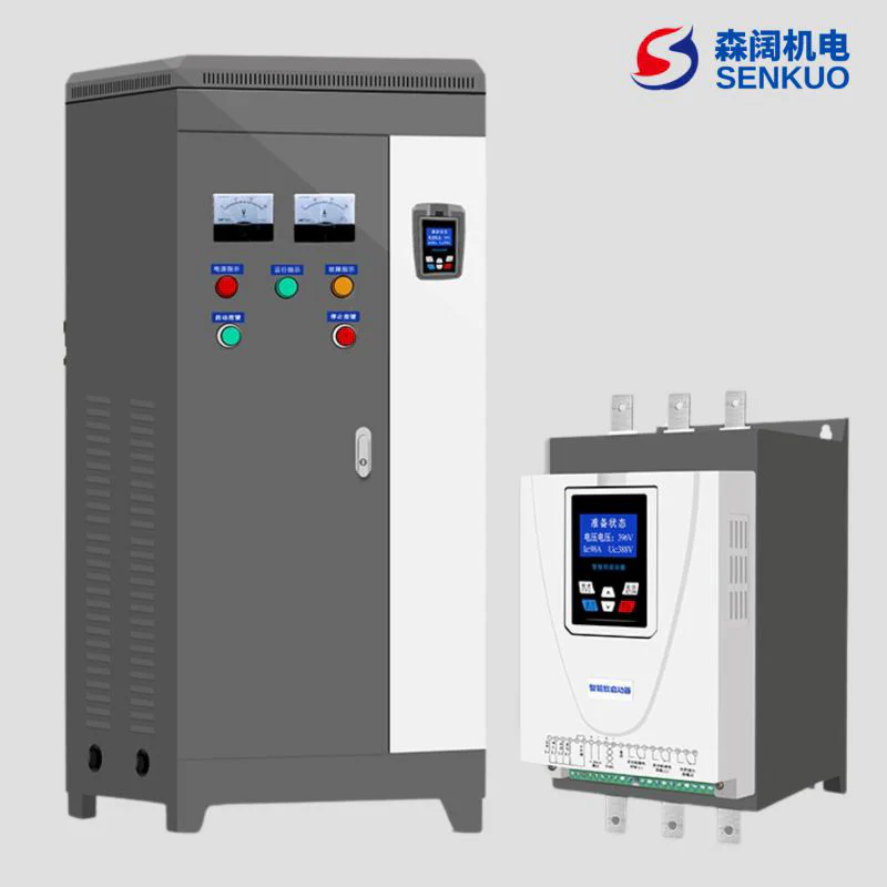
Intelligent AC Motor Soft Starter is a new type of motor starting equipment with international advanced level designed and produced using power electronics technology, microprocessor technology and modern control theory. This product can effectively limit the starting current of asynchronous motors and can be widely used in fans, pumps, conveyors, compressors and other loads. It is an ideal replacement product for traditional star/delta conversion, autotransformer step-down, magnetic control step-down and other step-down starting equipment.
1.1 Functions of GE300 Series Soft Starter
- Reduce the starting current of the motor, reduce the distribution capacity, and avoid capacity increase investment;
- Reduce starting stress, extend the service life of motors and related equipment;
- Smooth starting and soft stopping avoid the surge problem and water hammer effect of traditional starting equipment;
- Multiple starting modes and wide range of current and voltage settings, can adapt to multiple load occasions, improve processes;
- Perfect and reliable protection functions, more effectively protect the safety of motors and related equipment;
- Can be used in frequent starting and stopping occasions.
1.2 Features of GE300 Series Soft Starter
- GE300 series intelligent AC motor soft starters adopt high-performance microprocessor technology, with higher performance and wider voltage adaptation range.
- 6 starting modes can be selected, which can maximize the best starting effect of the motor.
- Original swing starting mode, good starting effect for eccentric load.
- Can realize positive and negative rotation with step frequency conversion jog function, can realize motor positive and negative rotation jog operation;
- Three stop modes can be selected: free stop, soft stop, DC brake stop;
- Online type and bypass type can be set freely.
- Two driving modes can be selected: torque mode and smooth mode.
- Two independent programmable output relays: can easily realize interlocking control with other equipment, and has delay action function, delay time adjustable.
- Can display three-phase current values at the same time, and current values can be independently calibrated.
- Large screen LCD human-machine interface, Chinese (Chinese display) and English two display modes, easy to operate.
- Multiple protection monitoring functions, thermal overload protection can be adjusted according to load requirements, multiple protections;
- Functions can be independently selected to open and close.
- Can query the last 12 fault records, provide fault analysis basis.
- A set of 4~20mA (0~20mA) analog output;
- MODBUSRTU communication (RS485), optional. Can enter parameter settings, operation and monitoring through the host computer, to achieve high intelligent control.
- Actual power setting: When the soft starter power is larger than the actual load power, the rated current of the soft starter can be set according to the actual load, so that the actual power of the soft starter matches the load, to ensure the accuracy of starting, operation, protection and other parameters.
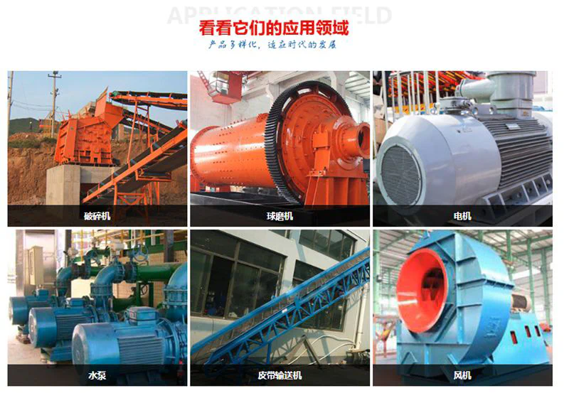
1.3 Application Scenarios
Soft starters are widely used in various industrial fields, such as pumps, fans, conveyors, compressors, etc., especially suitable for occasions that require frequent starting and stopping.
1.4 Notes
- Choose the right model: Choose the right soft starter model according to the motor power and starting requirements.
- Installation and maintenance: Install and maintain according to the manufacturer’s guidance to ensure the normal operation of the equipment.
- Environmental factors: Soft starters should be installed in a dry, dust-free, non-corrosive gas environment to extend the service life of the equipment.
2. Product Model
2.1 Product Label
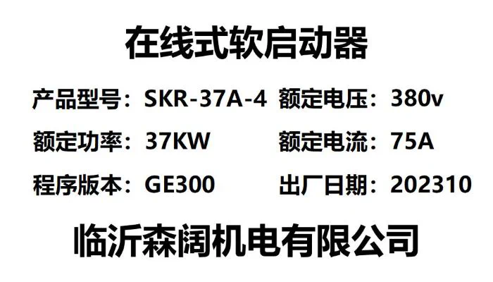 Each Intelligent AC Motor Soft Starter has undergone all functional and operational tests before leaving the factory. After receiving the equipment, please check according to the following steps. If you find any problems, please contact the supplier immediately. Check the product nameplate: Confirm whether the goods you received match the products you ordered.
2.2 Model Meaning
SKR-37A-4 online soft starter, each part of the model represents different meanings of the soft starter:
- SK: Represents the company name Senkuo.
- R: Represents soft start.
- 37: Represents the rated power of 37KW.
- A: A represents online soft starter, B represents bypass soft starter, C represents online soft start cabinet, D represents bypass soft start cabinet.
- 4: 2 represents 220V, 4 represents 380V, 6 represents 660V.
- Check whether the product is damaged during transportation, such as: internal parts falling off, shell depression, deformation and connection falling off and other problems.
- Product certificate and instruction manual: Each soft starter is enclosed with a product certificate and an instruction manual.
3. Usage Conditions and Installation
Usage conditions have a certain impact on the normal use and service life of the soft starter, so please install the soft starter in a place that meets the following usage conditions.
3.1 Product Usage Conditions
Power supply: Mains electricity, self-provided power station, diesel generator set; Input voltage: AC380V (-10%~+15%), 50Hz/60Hz; Applicable motor: General squirrel cage asynchronous motor (please specify when ordering winding motors): Starting frequency: Standard products are recommended to start and stop no more than 15 times per hour: Cooling method: Forced air cooling (thyristor online type) Natural air cooling (bypass type): Installation method: Wall-mounted; Usage conditions: Intelligent AC motor bypass soft starter should be equipped with bypass contactor when in use; Protection level: IP20 (55kW and below)/IP00 (75kW and above): Environmental conditions: Altitude below 2000 meters, reduce capacity accordingly if exceeding 2000 meters: ambient temperature between -25℃~+40℃; Relative humidity does not exceed 95% (20℃±5℃) no condensation; No flammable, explosive, corrosive gases, no conductive dust. Indoor installation, good ventilation. Vibration less than 0.5G.
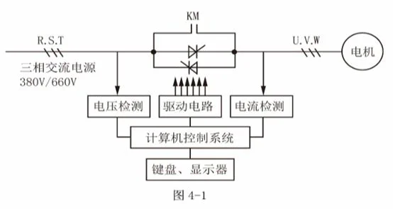
4. Working Principle
GE300 Series Intelligent AC Motor Soft Starter adopts three pairs of anti-parallel thyristors connected in series to the stator circuit of the AC motor. Using the electronic switching function of thyristors, the conduction degree of thyristors is changed by controlling the change of their trigger angles through the microprocessor, thereby changing the input voltage of the motor to achieve the purpose of controlling the soft starting of the motor. When the starting is completed, the soft starter output reaches the rated voltage. At this time, through the bypass control signal, the three-phase bypass contactor KM is automatically controlled to close, and the motor is put into the grid operation, as shown in Figure 4-1.
5. Terminal Wiring Diagram and Instructions
5.1 Soft Starter Terminal Wiring Diagram
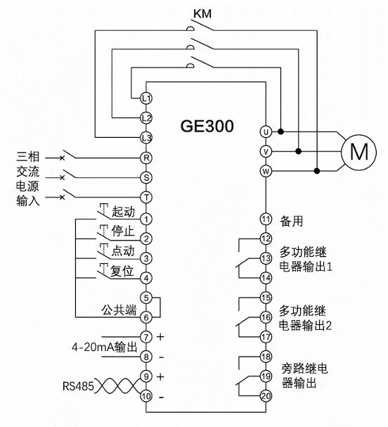 Note: Built-in bypass and online soft starters do not have L1, L2, L3 terminals, nor do they need to be connected to external AC contactor KM.
5.2 Soft Starter Secondary Terminal Sorting Diagram
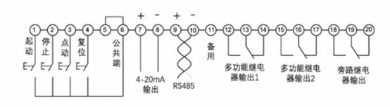 Note 1: Terminals 1-10 internally provide power, only need to connect switching quantity externally, no need to connect power.
Note 2: 12 to 20 need to provide external power and load to connect indicator light circuit diagram, etc.
Note 1: Terminals 1-10 internally provide power, only need to connect switching quantity externally, no need to connect power.
Note 2: 12 to 20 need to provide external power and load to connect indicator light circuit diagram, etc.
5.3 Soft Starter External Control Start-Stop Wiring Diagram
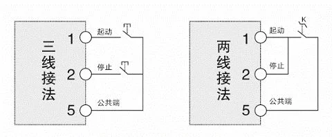 Note: Indicates that there are two wiring methods for external control start-stop signals. When using two-wire control, the stop terminal is connected to the start terminal.
5.4 Soft Starter External Terminal Instructions
| Terminal Type | Terminal No. | Terminal Name | Description |
|---|---|---|---|
| Main Circuit | R.S.T | Power Input | Soft starter three-phase AC power input |
| Main Circuit | U,V,W | Soft Starter Output | Connected to three-phase asynchronous motor |
| Main Circuit | L1,L2,L3 | Bypass Contactor Terminal | Used to connect bypass contactor. Only external bypass soft starters have this terminal, built-in bypass and thyristor online soft starters do not have this terminal |
| Digital Input | 1 | External Control Start | Short-circuit with common terminal (5, 6) to start the soft starter |
| Digital Input | 2 | External Control Stop | Disconnect with common terminal (5, 6) to stop the soft starter |
| Digital Input | 3 | External Control Jog | Short-circuit with common terminal (5, 6) to jog start the soft starter |
| Digital Input | 4 | External Control Fault Reset | Short-circuit with common terminal (5, 6) to clear the fault state when there is a fault |
| Digital Input | 5 | Digital Input Common Terminal | Common terminal for digital input terminals |
| Digital Input | 6 | Digital Input Common Terminal | Common terminal for digital input terminals |
| Analog Output | 7 | 4-20mA Output Positive | 4-20mA output, 20mA corresponding current can be adjusted through parameters C26,C27,C28 |
| Analog Output | 8 | 4-20mA Output Negative | 4-20mA output, 20mA corresponding current can be adjusted through parameters C26,C27,C28 |
| Communication | 9 | RS485+ | Used for ModBus RTU communication |
| Communication | 10 | RS485- | Used for ModBus RTU communication |
| Spare | 11 | Spare | No function, reserved |
| Programming Relay 1 | 12 | Programming Relay 1 Normally Open | Programmable output, can be selected from the following functions:0. No action1. Power on action2. Soft starting action3. Bypass action4. Soft stopping action5. Jogging action6. Running action7. Standby action8. Fault action9. Thyristor breakdown action10. Current greater than arrival value 111. Current greater than arrival value 212. Current less than arrival value 113. Current less than arrival value 2 |
| Programming Relay 1 | 13 | Programming Relay 1 Common | Same as above |
| Programming Relay 1 | 14 | Programming Relay 1 Normally Closed | Same as above |
| Programming Relay 2 | 15 | Programming Relay 2 Normally Open | Same as above |
| Programming Relay 2 | 16 | Programming Relay 2 Common | Same as above |
| Programming Relay 2 | 17 | Programming Relay 2 Normally Closed | Same as above |
| Bypass Relay | 18 | Bypass Relay Normally Open | Closed when bypass is running |
| Bypass Relay | 19 | Bypass Relay Common | Closed when bypass is running |
| Bypass Relay | 20 | Bypass Relay Normally Closed | Closed when bypass is running |
6. Keyboard Functions and Operations
6.1 Keyboard Hole Opening
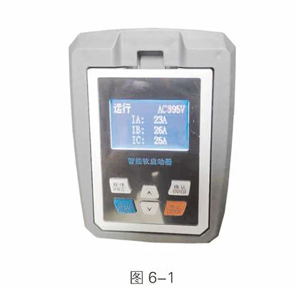
Soft Starter adopts a large screen LCD display module and micro-motion buttons to form an operation display keyboard. 6 micro-motion buttons can realize the start, stop operation, parameter setting, modification, fault query, fault reset and other operations of the soft starter. See Figure 6-1 for details
 Online soft start cabinet door opening size 120x75mm
Bypass soft start cabinet door opening size 110x88mm
Online soft start cabinet door opening size 120x75mm
Bypass soft start cabinet door opening size 110x88mm
6.2 Keyboard Operation
- Press the “Program” key to enter the parameter group, press the “△” key to switch parameter groups.
- Parameter modification, press the first step to enter the corresponding parameter, press the “Program” key to enter the parameter, press the “△” key to modify the parameter value, after modification, press the “Confirm” key to save the parameter, press the “Confirm” key again to return to the main interface.
- Press the “Run” key to start the soft starter.
- Press the “Stop” key to stop.
- Press the “Confirm” key in standby state to view fault records.
- Long press the “△” key to clear fault records.
- Long press “V” to restore factory settings.
7. Soft Start Parameter Function Table
A Basic Parameter Table
| Serial No. | Parameter Name | Parameter Range | Default Value | Notes | Attribute |
|---|---|---|---|---|---|
| 1 | Control Mode | 0:Prohibit start-stop1:Keyboard control only2:External control only3:Keyboard+External control4:Communication control only5:Keyboard+Communication6:External control+Communication7:Keyboard+External control+Communication | 3:Keyboard+External control | ✅ | |
| 2 | Starting Mode | 0:Current limiting start1:Voltage ramp start2:Reserved3:Jump voltage ramp start | 0:Current limiting start | ✅ | |
| 3 | Starting Current Limiting Percentage | 50%~600% | 300% | ✅ | |
| 4 | Starting Voltage Percentage | 10%~80% | 35% | ✅ | |
| 5 | Voltage Ramp Starting Time | 1s~120s | 15s | ✅ | |
| 6 | Jump Voltage | 10%~95% | 80% | ✅ | |
| 7 | Jump Time | 10ms~2000ms | 500ms | ✅ | |
| 8 | Stop Mode | 0:Free stop1:Soft stop | 0:Free stop | ✅ | |
| 9 | Soft Stop Time | 1s~60s | 5s | ✅ | |
| 10 | Soft Starter Type | 0: Online type1: Bypass type | 1: Bypass type | ✅ |
✅:Indicates that the set value of this parameter can be changed when the soft starter is in stop or running state; ✳️:Indicates that the set value of this parameter cannot be changed when the soft starter is in running state; ❎:Indicates that the value of this parameter is an actual detection record value and cannot be changed;
B Protection Parameter List
| Serial No. | Parameter Name | Parameter Range | Default Value | Notes | Attribute |
|---|---|---|---|---|---|
| 1 | Starting Overload Level | 0~30 | 10 | 0:Closed | ✅ |
| 2 | Running Overload Level | 0~30 | 10 | 0:Closed | ✅ |
| 3 | Running Overcurrent Multiple | 0%-600% | 0% | 0:Closed | ✅ |
| 4 | Running Overcurrent Protection Time | 0s-6000s | 5s | ✅ | |
| 5 | Overvoltage Protection Value | 100%~140% | 120% | 100:Closed | ✅ |
| 6 | Overvoltage Protection Time | 1s~60s | 5s | ✅ | |
| 7 | Undervoltage Protection Value | 60%-100% | 80% | 100:Closed | ✅ |
| 8 | Undervoltage Protection Time | 1s~60s | 5s | ✅ | |
| 9 | Three-Phase Imbalance Degree | 20%~100% | 40% | 100:Closed | ✅ |
| 10 | Three-Phase Imbalance Time | 0.1s~60.0s | 10.0s | ✅ | |
| 11 | Starting Timeout Time | 0s~150s | 60s | 0:Closed | ✅ |
| 12 | Jog Timeout Time | 0s~150s | 0s | 0:Closed | ✅ |
| 13 | Underload Protection Value | 0%~100% | 0% | 0:Closed | ✅ |
| 14 | Underload Protection Time | 1s~60s | 10s | ✅ |
✅:Indicates that the set value of this parameter can be changed when the soft starter is in stop or running state; ✳️:Indicates that the set value of this parameter cannot be changed when the soft starter is in running state; ❎:Indicates that the value of this parameter is an actual detection record value and cannot be changed;
C Advanced Function List
| Serial No. | Parameter Name | Parameter Range | Default Value | Notes | Attribute |
|---|---|---|---|---|---|
| 1 | Programmable Relay 1 | Function:0:No action1:Power on action2:Soft starting action3:Bypass action4:Soft stopping action5:Jogging action6:Running action7:Standby action8:Fault action9:Thyristor breakdown action | 8:Fault action | ✳️ | |
| 2 | Programmable Output Delay 1 | 0-600s | 0s | ✳️ | |
| 3 | Programmable Relay 2 | Function:0:No action1:Power on action2:Soft starting action3:Bypass action4:Soft stopping action5:Jogging action6:Running action7:Standby action8:Fault action9:Thyristor breakdown action | 6:Running action | ✳️ | |
| 4 | Programmable Output Delay 2 | 0-600s | 0s | ✳️ | |
| 5 | Communication Address | 1-127 | 1 | ✳️ | |
| 6 | Communication Baud Rate | 0:24001:48002:96003:19200 | 2:9600 | ✳️ | |
| 7 | Phase A Current Calibration Value | 10%~1000% | 100% | ✳️ | |
| 8 | Phase B Current Calibration Value | 10%~1000% | 100% | ✳️ | |
| 9 | Phase C Current Calibration Value | 10%~1000% | 100% | ✳️ | |
| 10 | Input Voltage Calibration Value | 10%~1000% | 100% | ✳️ | |
| 11 | 4-20mA Lower Limit Calibration | 0%~150.0% | 20.0% | ✳️ | |
| 12 | 4-20mA Upper Limit Calibration | 0%~150.0% | 100% | ✳️ | |
| 13 | 4-20mA Upper Limit Current | 50%~500% | 200% | ✳️ |
✅:Indicates that the set value of this parameter can be changed when the soft starter is in stop or running state; ✳️:Indicates that the set value of this parameter cannot be changed when the soft starter is in running state; ❎:Indicates that the value of this parameter is an actual detection record value and cannot be changed;
D Status Information List
| Serial No. | Parameter Name | Parameter Range | Default Value | Notes | Attribute |
|---|---|---|---|---|---|
| 1 | Soft Start Rated Current | ❎ | |||
| 2 | Soft Start Rated Voltage | ❎ | |||
| 3 | Motor Rated Current | 10-1600A | ✳️ | ||
| 4 | Soft Start Starting Times | ❎ | |||
| 5 | Cumulative Running Hours | ❎ | |||
| 6 | Main Control Software Version | ❎ |
✅:Indicates that the set value of this parameter can be changed when the soft starter is in stop or running state; ✳️:Indicates that the set value of this parameter cannot be changed when the soft starter is in running state; ❎:Indicates that the value of this parameter is an actual detection record value and cannot be changed;
E Display Parameter List
| Serial No. | Parameter Name | Parameter Range | Default Value | Notes | Attribute |
|---|---|---|---|---|---|
| 1 | Standby Display Mode | 0:Mode 01:Mode 1 | 0:Mode 0 | ✳️ | |
| 2 | Running Display Mode | 0:Mode 01:Mode 1 | 0:Mode 0 | ✳️ | |
| 3 | Operation Language Selection | 0:English1:Chinese | 1:Chinese | ✳️ | |
| 4 | Screen Protection Time | 0s~1800s | 120s | 0:No protection | ✳️ |
| 5 | Keyboard Software Version | ❎ | |||
| 6 | Screen Contrast | ❎ |
✅:Indicates that the set value of this parameter can be changed when the soft starter is in stop or running state; ✳️:Indicates that the set value of this parameter cannot be changed when the soft starter is in running state; ❎:Indicates that the value of this parameter is an actual detection record value and cannot be changed;
8. Soft Start Parameter Description
8.1 Starting Modes
Intelligent AC Motor Soft Starter has the following 6 starting modes, users can choose according to their own load conditions. 0:Current limiting starting 1:Voltage ramp starting 2:Reserved 3:Jump current limiting starting 4:Jump voltage ramp starting 5:Jog starting 6:Swing starting Except for jog starting, all starting modes are limited by B10. Starting timeout time. When the starting time exceeds the starting timeout time limit, the soft starter reports a starting timeout fault and stops. When B10 is set to 0, it means that the starting timeout protection is closed.
8.1.1 Current Limiting Starting
After starting, the motor current quickly rises to the set current limiting value Im, and keeps the output current not greater than this value, so that the motor gradually accelerates and the voltage gradually rises. When the motor approaches the rated speed, the motor current quickly drops to the rated current le, completing the starting process, as shown in Figure 8-1.
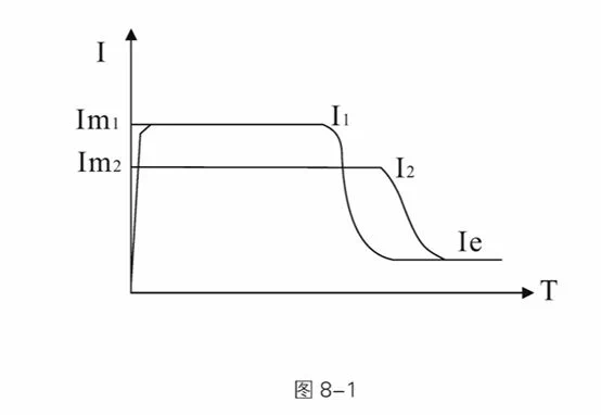
Current limiting starting mode is generally used in occasions with strict requirements on starting current, especially when the grid capacity is small and the starting capacity needs to be limited. The current limiting multiple can be set according to requirements, generally between 2.5 and 3 times. If the setting is too small, it will also cause failure to start normally. When using current limiting starting, the starting time is related to the size of the current limiting multiple. The larger the current limiting multiple, the shorter the starting time, and vice versa.
Parameters related to “current limiting starting”:
A01. Starting mode, A02. Starting current limiting percentage
8.1.2 Voltage Ramp Starting
After starting, the soft starter outputs voltage, quickly rises to the “starting voltage” value U1, and then gradually increases the output voltage according to the “voltage ramp starting time” until the starting is completed, as shown in Figure 8-2.
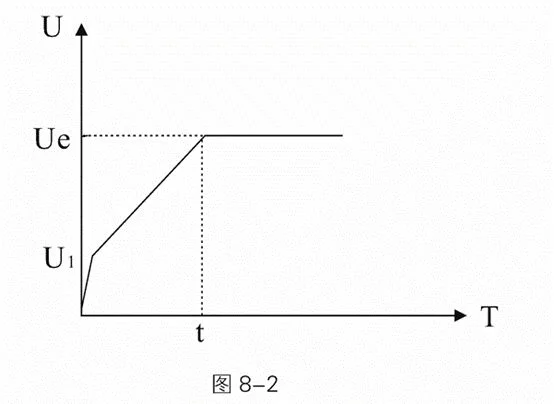
Voltage ramp starting mode is suitable for large inertia loads, or occasions with no strict requirements on starting current but high requirements on starting smoothness. This starting mode can greatly reduce starting impact and mechanical stress. The larger the initial voltage U1 value, the larger the starting initial torque, but the larger the starting instant impact. Voltage ramp starting is also controlled by current limiting starting multiple, that is, the starting current will not exceed the starting current limiting value during voltage ramp starting. This measure is to prevent damage to the system due to improper parameter settings, so the starting current limiting value should be appropriately increased when using voltage ramp mode. The length of the starting process is related to the starting time setting and the weight of the load.
Parameters related to “voltage ramp starting”:
A01. Starting mode, A03. Starting voltage percentage, A04. Voltage ramp starting time, A02. Starting current limiting percentage
8.1.3 Jump Current Limiting Starting
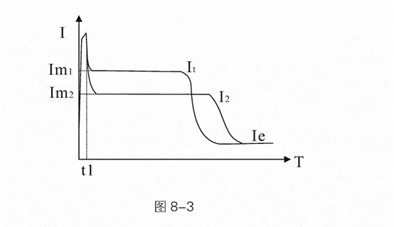
For some loads with large static resistance, a larger torque is needed at the moment of starting to start normally. This starting mode can be selected. When starting, the soft starter instantly outputs a higher voltage (time can be set) to make the motor rotate, and then starts according to the current limiting starting mode until the starting is completed, as shown in Figure 8-3.
 Parameters related to “jump voltage ramp starting”:
A01. Starting mode, A02. Starting current limiting percentage, A05. Jump voltage, A06. Jump time
Parameters related to “jump voltage ramp starting”:
A01. Starting mode, A02. Starting current limiting percentage, A05. Jump voltage, A06. Jump time
8.1.4 Jump Voltage Ramp Starting
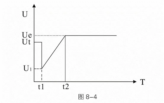
For some loads with large static resistance, a larger torque is needed at the moment of starting to start normally. This starting mode can be selected. When starting, the soft starter instantly outputs a higher voltage (time can be set) to make the motor rotate, and then starts according to the voltage ramp starting mode until the starting is completed, as shown in Figure 8-4.
 Parameters related to “jump voltage ramp starting”:
A01. Starting mode, A03. Starting voltage percentage, A04. Voltage ramp starting time, A02. Starting current limiting percentage, A05. Jump voltage, A06. Jump time
Parameters related to “jump voltage ramp starting”:
A01. Starting mode, A03. Starting voltage percentage, A04. Voltage ramp starting time, A02. Starting current limiting percentage, A05. Jump voltage, A06. Jump time
8.1.5 Jog Starting
The jog function is mainly used for some load positioning or test run functions. This mode can be divided into step-down mode jog and step-down frequency mode jog, where step-down frequency mode jog includes three frequencies of step-down forward rotation and three modes of step-down reverse rotation. In the step-down forward rotation mode, step-down forward rotation 1 is the fastest, and step-down forward rotation 3 is the slowest; in the step-down reverse rotation mode, step-down reverse rotation 1 is the fastest, and step-down reverse rotation 3 is the slowest. In step-down jog, the output voltage of the soft starter quickly increases to the jog voltage Up (A08) and remains unchanged. Changing the setting value of the jog voltage Up can change the output torque of the motor during jog. In step-down frequency jog mode, the output torque of the motor can be adjusted by A09 low-frequency jog strength. The larger this value, the larger the output torque and the larger the output current. The jog time is limited by B11. Jog timeout time. When the jog time exceeds the jog timeout time value, the soft starter reports a jog timeout fault and stops. Adjusting parameter B11 to 0 means closing the jog timeout protection.
8.1.6 Swing Starting
Aiming at the problem that large inertia and eccentric loads such as ball mills are difficult to start, this series of soft starters provides a swing starting function, which can make the load start smoothly by swinging back and forth several times.
The basic starting mode adopted by swing starting is the current limiting mode, and the number of starting times can be set from 1 to 4 times. Each time, the starting time and stopping time can be set independently. The soft starter will be based on the actual completion of starting, and will not rigidly follow the set number of swings to start. For example, if 4 swing starts are set but only 2 swings are actually needed to complete the start, the soft starter will enter the running state after two starts and will not execute the remaining swing times. The swing starting mode is shown in Figure 8-5.
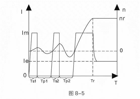 In the figure: 1 represents motor current, le represents motor rated current, Im represents starting current limiting value, n represents motor speed, nr represents motor rated speed, T represents starting time, Ts1, Ts2 represent first and second swing starting times, Tp1, Tp2 represent first and second swing stopping times, Tr represents starting completion time. This figure is an example of setting the number of swings to 2 times.
Parameters related to swing starting are as follows: A01. Starting mode, A02. Starting current limiting percentage, C11. Number of swings, C12~C19. Swing starting time and swing stopping time
8.2 Stop Modes
The soft starter has the following three stop modes:
- 0:Free stopping
- 1:Soft stopping
- 2:DC brake stopping
8.2.1 Free Stopping
When receiving a stop command, the soft starter controls the bypass contactor to disconnect, and at the same time, blocks the output voltage of the main circuit thyristor, and the motor gradually stops according to inertia.
8.2.2 Soft Stopping
In this stopping mode, the motor power supply is switched from the bypass contactor to the main circuit thyristor, and the output voltage is gradually reduced until the motor stops smoothly. This mode is generally used to prevent the water hammer phenomenon that occurs at the moment when vertical water supply pipeline equipment stops horizontally, extending the service life of pipeline valves. Parameters related to soft stopping: A10. Stop mode, A11. Soft stop time
8.2.3 DC Brake Stopping
In this stopping mode, the motor power supply is switched from the bypass contactor to the main circuit thyristor, and the soft starter controls the output of DC voltage for motor brake stopping, shortening the running time of the motor from rotating state to stationary state. This mode is generally used in occasions with requirements on motor stopping time, which can make large inertia loads completely stop in a shorter time. C04. DC brake strength is used to control the magnitude of DC brake torque. The larger this parameter value, the larger the brake torque and brake current, and the shorter the brake time. C05. DC brake time is used to adjust the time for applying brake current. The longer the time, the lower the remaining speed of the motor after braking. Parameters related to DC brake stopping: A10. Stop mode, C04. DC brake strength, C05. DC brake time
8.3 Soft Starter Type Selection
Parameter A12. Soft starter type is used to select the soft starter type, which can be selected between online type and bypass type. The thyristor of the online soft starter remains triggered in the running state, which is used for the online operation of the soft starter. While the bypass type (including built-in bypass and external bypass) stops triggering the thyristor in the running state, and the main circuit is connected by the bypass contactor for full voltage operation of the motor.
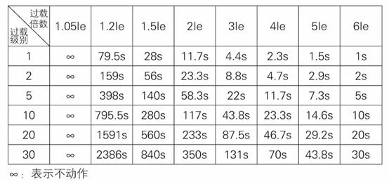
8.4 Overload Protection
Overload protection adopts inverse time limit control
Protection time: t=$\frac{35*Tp}{(I/Ip)²-1}$
Where: t represents action time, Tp represents protection level, I represents running current, Ip represents motor rated current
8.5 Motor Overload Protection Characteristic Curve
Motor overload protection characteristic curve: Figure 8-6
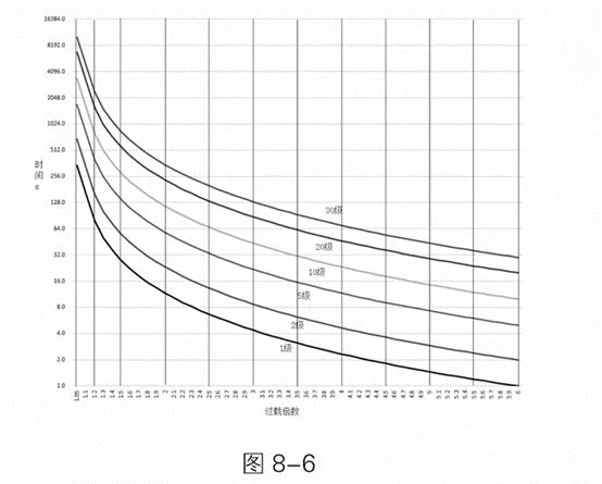
Motor Overload Protection Characteristics
8.5 Current Arrival Function
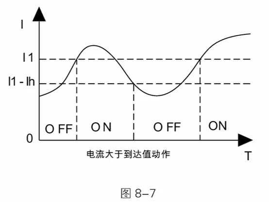
The current arrival function is used with two multi-functional relays, which is divided into two modes: relay action when current is greater than arrival value and relay action when current is less than arrival value.
In the mode of relay action when current is greater than arrival value, the relay acts when the running current is greater than the current arrival setting value, and the relay recovers when the running current is less than (current arrival value - current arrival hysteresis value), as shown in Figure 8-7.
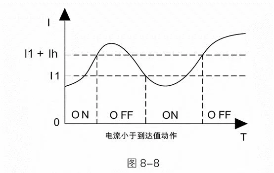
 In the mode of relay action when current is less than arrival value, the relay acts when the running current is less than the current arrival setting value, and the relay recovers when the running current is greater than (current arrival value + current arrival hysteresis value), as shown in Figure 8-8.
 Parameters related to the current arrival function:
C00. Programmable relay 1, C01. Programmable output delay 1, C02. Programmable relay 2, C03. Programmable output delay 2, C06. Current arrival 1, C07. Current arrival hysteresis 1, C08. Current arrival 2, C09. Current arrival hysteresis 2
In the figure: 11 represents current arrival value, Ih represents hysteresis current, ON represents relay action, OFF represents relay recovery.
Parameters related to the current arrival function:
C00. Programmable relay 1, C01. Programmable output delay 1, C02. Programmable relay 2, C03. Programmable output delay 2, C06. Current arrival 1, C07. Current arrival hysteresis 1, C08. Current arrival 2, C09. Current arrival hysteresis 2
In the figure: 11 represents current arrival value, Ih represents hysteresis current, ON represents relay action, OFF represents relay recovery.
8.6 Driving Mode
Parameter C10. Driving mode is used to select the driving mode of the soft starter, which can select 0 torque mode and 1 smooth mode. The torque mode has a larger motor starting torque, but there may be larger current fluctuations during the starting process, which is mainly used in occasions where starting is difficult and requires large starting torque; while the smooth mode has stable motor starting current, more precise control, and smaller impact on mechanical load and power grid during starting, which is suitable for most occasions.
8.7 Analog Current Output Function
The analog current output function can realize analog 4-20mA, 0-20mA and other current output functions. C28.4-20mA upper limit current: used to set the soft starter current corresponding to the analog current output upper limit. C27.4-20mA upper limit calibration: used to set the analog current output upper limit value, 100% represents 20mA. C26.4-20mA lower limit calibration: used to set the analog current output upper limit value, 20% represents 4mA. Example of analog current output parameter setting: Example 1: 20mA corresponds to 2 times motor rated current, 4mA corresponds to 0A C28=200%, C26=20%, C27=100% Example 2: 20mA corresponds to 1 time motor rated current, 0mA corresponds to 0A C28=100%, C26=0%, C27=100% Note: If there is a deviation in the analog current output, parameters C26 and C27 can also be used for fine adjustment.
8.8 Screen Protection Time
The screen protection time is used to set the screen backlight on time. After the last keyboard operation, the screen backlight turns off after E03. Screen protection time to save energy and extend the service life of the screen backlight. Setting E03. Screen protection time to 0 can turn off this function, and the screen always remains on.
8.9 Screen Contrast
If the screen display is too light or too dark, you can use parameter E05. Screen contrast to adjust the screen contrast.
8.10 Communication Function
The soft starter can have built-in ModbusRTU communication function (please specify when ordering), please refer to the communication manual for the communication protocol.
9. Fault Handling
| Serial No. | Fault Name | Possible Fault Causes | Solution |
|---|---|---|---|
| 1 | Input Phase Loss | Incoming power phase loss | Check whether there is a phase loss phenomenon in the upper three-phase power supply, whether the upper power incoming line is connected well, and whether the upper circuit breaker is good |
| 2 | Output Phase Loss | Lower phase loss | Check whether the lower motor wiring is good and whether the motor has faults |
| 3 | Running Overload | 1. Motor overload operation2. Motor rated current setting is incorrect3. Running overload level selection is inappropriate4. Current display is inaccurate | 1. Check the load situation, whether there is a phenomenon of excessive load2. Check whether parameter D02 is set correctly3. Check whether parameter B01 is set appropriately4. Adjust parameters C22, C23, C24 to make the soft starter three-phase display current equal to the actual current |
| 4 | Starting Overload | 1. Motor overload starting2. Motor rated current setting is incorrect3. Running overload level selection is inappropriate4. Current display is inaccurate | 1. Check the load situation, whether there is a phenomenon of excessive load2. Check whether parameter D02 is set correctly3. Check whether parameter B00 is set appropriately4. Adjust parameters C22, C23, C24 to make the soft starter three-phase display current equal to the actual current |
| 5 | Soft Start Underload | 1. Incorrect motor underload parameter setting2. Inaccurate current display | 1. Adjust parameters B12, B13 to appropriate values2. Adjust parameters C22, C23, C24 to make the soft starter three-phase display current equal to the actual current |
| 6 | Current Imbalance | 1. Motor coil has problems2. Main line terminal contact is poor3. Current display is inaccurate | 1. Replace or repair the motor2. Re-tighten each terminal3. Adjust parameters C22, C23, C24 to make the soft starter three-phase display current equal to the actual current |
| 7 | Soft Start Overheating | 1. The soft starter starts too frequently2. The external environment temperature of the soft starter is too high3. There are components with large heat generation around the soft starter and the installation is too compact | 1. Increase the starting interval time, wait for the soft starter to cool down before starting next time, or add cooling devices to make the soft starter cool down more quickly2. Improve the external environment of the soft starter, or use it with reduced capacity3. Improve the layout or strengthen the cooling intensity in the cabinet |
| 8 | Overvoltage Fault | 1. Power supply voltage is too high2. Voltage display is inaccurate | 1. Adjust transformer power supply voltage2. Adjust parameter C25 to make the soft starter display voltage consistent with the actual voltage |
| 9 | Undervoltage Fault | 1. Power supply voltage is too low2. Voltage display is inaccurate | 1. Adjust transformer power supply voltage; check whether the incoming cable is too small, check whether the transformer power margin is too small2. Adjust parameter C25 to make the soft starter display voltage consistent with the actual voltage |
| 10 | Thyristor Breakdown | Two-phase thyristor breakdown, current flows through the soft starter in the stop state | If there is current in the stop state, this fault will be reported, power off, check whether two-phase thyristors have breakdown phenomenon |
| 11 | Starting Timeout | Starting time exceeds B10 setting value | 1. Check whether parameter B10 setting is appropriate2. Check whether the load is too heavy, resulting in too long starting time3. Appropriately adjust starting parameters to shorten starting time |
| 12 | Jog Timeout | Jog time exceeds B11 setting value | 1. Check whether parameter B10 setting is appropriate2. Shorten jog operation time |
| 13 | Running Overcurrent | 1. Running current is too large2. Motor rated current setting is incorrect3. Running overcurrent value setting is incorrect3. Current display is inaccurate | 1. Check the load situation, whether there is a phenomenon of excessive load2. Check whether parameter D02 is set correctly3. Check whether parameters B02, B03 are set appropriately4. Adjust parameters C22, C23, C24 to make the soft starter three-phase display current equal to the actual current |
| 14 | Internal Fault | The soft starter sends internal hardware fault | Try to power on again to see if it is solved, if not solved, please contact the manufacturer |
10. Operation and Daily Maintenance
10.1 Trial Run Inspection and Precautions
For safe operation, check according to the following items before power on.
- Does the soft start power match the motor power? The motor rated current can be set according to the motor nameplate current value through D02. Motor rated current item.
- Is the motor insulation up to standard?
- Is the main circuit input and output wiring correct? - Are all wiring nuts tightened?
- Use a multimeter to check whether the three-phase incoming power (R, S, T) has a short circuit phenomenon?
- After power on, displaying “Standby” indicates that it is in normal ready to start state. You can use “Jog” mode to check whether the motor rotation direction is correct. If not, you can swap any two phases at the motor end.
- During the trial run, if the motor starting state is not ideal, you can set the start-stop parameters according to the parameter table, and make corresponding modifications to the starting mode, current, voltage, time and other parameters.
- If fault protection occurs during the entire power-on and operation process, it will display the fault state. Please handle it according to the corresponding prompts in Chapter 9.
- After the soft starter is powered on, please do not open the cover to avoid electric shock.
- During the trial run, if abnormal phenomena such as abnormal sounds, smoke or abnormal smell are found, stop immediately, cut off the power supply, and check the cause.
- When the soft starter output is not connected to the motor, there will be induced voltage in U, V, W three phases, which is a normal phenomenon. This induced voltage will disappear after the motor is connected.
10.2 Daily Maintenance Precautions
- Induced voltage: After the intelligent AC motor soft starter is connected to the power supply at the input end, when the load is open, even in the stop state, there will be induced voltage at its output end, which is caused by the leakage current of the thyristor and is a normal phenomenon; this induced voltage will disappear after the motor is connected, so attention should be paid to the danger of electric shock during use.
- Reactive power compensation: If reactive power compensation circuit for improving power factor is needed in the distribution circuit, the reactive power compensation capacitor should be connected to the input end of the soft starter, not to its output end, otherwise it will cause damage to the power devices of the soft starter.
- Insulation test: It is strictly prohibited to use a megger to measure the insulation resistance between the input and output of the motor soft starter, otherwise the power devices and control board of the soft starter may be damaged due to overvoltage.
- Circuit wiring: The input and output of the motor soft starter cannot be connected reversely, otherwise it may damage the soft starter or motor.
- Bypass contactor wiring: When the motor soft starter is equipped with a bypass contactor, the phase sequence of the soft starter output U, V, W and bypass output L11, L21, L31 must be consistent.
- External control terminal: The external control terminals of the intelligent AC motor soft starter, start, stop, jog, reset, common, must not introduce external power supply, otherwise it will damage the soft starter control board.
- In working conditions with more dust, regular dust cleaning should be carried out, otherwise the insulation level and heat dissipation effect of the soft starter will be reduced, causing faults or damage.
- In a humid environment, if the soft starter is not used for a long time, dehumidification treatment (such as drying with a hair dryer or electric furnace) must be carried out before use, otherwise the insulation level of the soft starter will be reduced due to moisture or condensation, causing creepage, short circuit, and damage to the soft starter.
10.3 Ordering Instructions
- When ordering, users should inform the supplier of the product model, specification, load situation and use conditions, so as to correctly select the product.
- External products of intelligent AC motor soft starters should be equipped with bypass contactors when in use.
- Users with special use conditions or requirements for this product, please indicate when ordering.
- If the load is a wound motor, please indicate when ordering. - If RS485 communication is needed, please indicate when ordering.
11. Soft Start Structure and Outline Dimensions
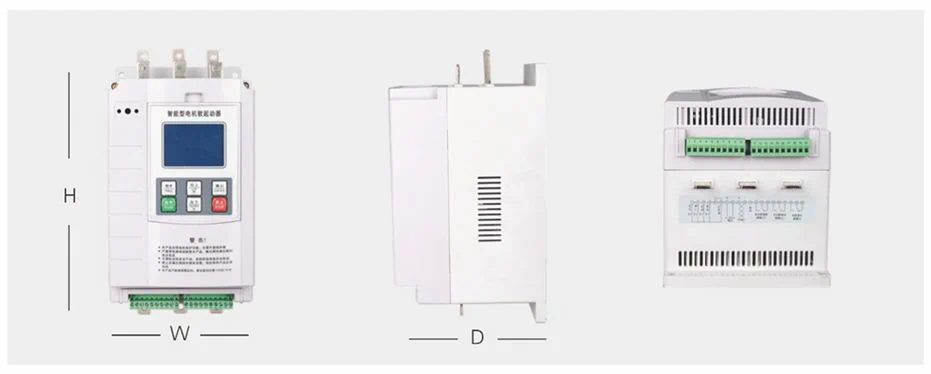
11.1 Online Soft Starter Outline Dimensions
5.5kW~55kW Online Soft Starter Outline Diagram
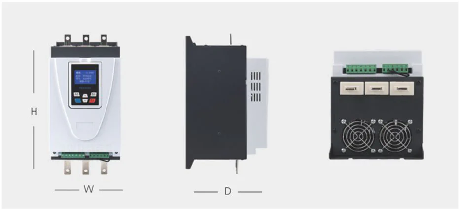
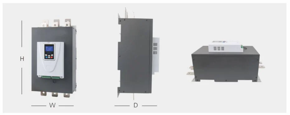
75kW-630kW Online Soft Starter Outline Diagram
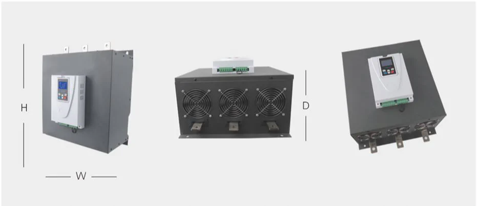
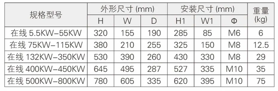
Online Soft Starter Dimension Diagram
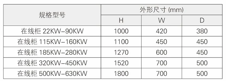
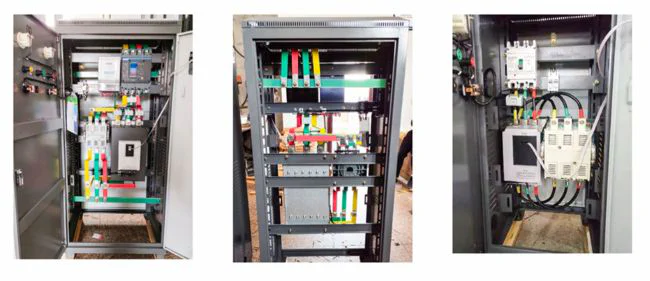
11.2 Online Soft Start Cabinet Outline Dimensions
Online Soft Start Cabinet Outline Diagram
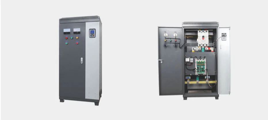
Online Soft Start Cabinet Dimension Diagram
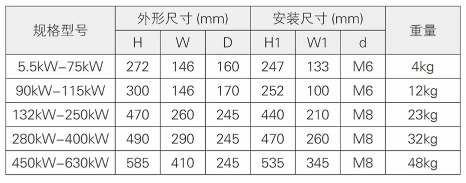
11.3 Bypass Soft Starter Outline Dimensions
5.5kW~75kW Bypass Soft Starter Outline Diagram
90kW-630kW Bypass Soft Starter Outline Diagram
Bypass Soft Starter Dimension Diagram
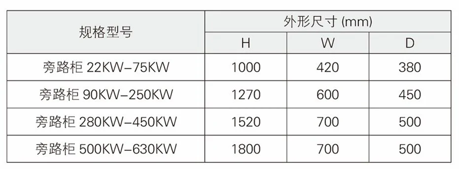
11.4 Bypass Soft Start Cabinet Outline Dimensions
12. Get Installation Support
Need further support?
Quick Support Channels
Installation Support Hotline
+86 150-6499-9739
Monday-Friday: 9:00 - 18:00
Remote Assistance
support@lyskjd.com
Apply for remote support
On-site Service
sales@lyskjd.com
Apply for on-site installation